6
. HYDRAULIC SYSTEM
6-
1-
6
6
-1-1
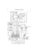
Control Valve Operation
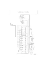
1) Oil Flow from Hydraulic Pump
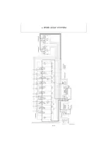
(1) Oil flow from piston pump P2
The oil from the piston pump P2 flows to the sections
through the port P2 of the inlet section and the parallel
passage.
The travel (L) section is positioned the most upstream in
the control valve, and then the swing, arm and P.T.O.
sections are arranged in that order.
The P.T.O. section is supplied with the oil from both the
piston pumps P1 and P2.
(2) Oil flow from piston pump P1
The oil from the piston pump P1 flows to the sections
through the port P1 of the inlet section and the parallel
passage.
The track gauge change section is positioned the most
upstream in the control valve, and then the boom swing,
boom, bucket, travel (R) and blade sections are
arranged in that order.
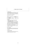
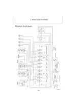
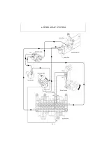
2) Simultaneous Operation of Boom and Bucket
The parallel passage in the bucket section has a throttle
Ø1.4 mm so that the oil can flow to the boom section
more smoothly than to the bucket section even when the
boom is given a heavy load. Therefore, the boom and
the bucket can be operated simultaneously.
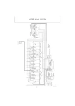
3) Simultaneous Operation of Travel and Blade
When the blade is operated while the machine is travel-
ing, the blade cylinder is supplied with the same quantity
of oil from the piston pumps P1 and P2 each through the
throttles in the parallel passage. Therefore, the blade
can be operated while the machine is traveling, with no
travel deviation. However, the travel speed is slowed
down.
Содержание ViO12-2A
Страница 1: ...SERVICE MANUAL EXCAVATOR ViO12 2A...
Страница 2: ......
Страница 3: ......
Страница 9: ......
Страница 21: ......
Страница 23: ......
Страница 37: ......
Страница 55: ......
Страница 57: ......
Страница 99: ......
Страница 109: ...5 3 1 5 ELECTRIC SYSTEM 5 3 Wiring Diagram...
Страница 114: ......
Страница 117: ...6 HYDRAULIC SYSTEM 6 1 3...
Страница 118: ...6 HYDRAULIC SYSTEM 6 1 4...
Страница 119: ...6 HYDRAULIC SYSTEM 6 1 5 This Page Intentionally Left Blank...
Страница 121: ...6 HYDRAULIC SYSTEM 6 1 7...
Страница 122: ...6 HYDRAULIC SYSTEM 6 1 8...
Страница 123: ...6 HYDRAULIC SYSTEM 6 2 1 6 2 Hydraulic Circuit Schematic...
Страница 125: ...6 HYDRAULIC SYSTEM 6 3 2...
Страница 126: ...6 HYDRAULIC SYSTEM 6 3 3...
Страница 127: ...6 HYDRAULIC SYSTEM 6 3 4 This Page Intentionally Left Blank...
Страница 129: ...6 HYDRAULIC SYSTEM 6 3 6...
Страница 130: ...6 HYDRAULIC SYSTEM 6 3 7...
Страница 131: ...6 HYDRAULIC SYSTEM 6 3 8 This Page Intentionally Left Blank...
Страница 133: ...6 HYDRAULIC SYSTEM 6 3 10...
Страница 134: ...6 HYDRAULIC SYSTEM 6 3 11...
Страница 135: ...6 HYDRAULIC SYSTEM 6 3 12 This Page Intentionally Left Blank...
Страница 137: ...6 HYDRAULIC SYSTEM 6 3 14...
Страница 138: ...6 HYDRAULIC SYSTEM 6 3 15...
Страница 139: ...6 HYDRAULIC SYSTEM 6 3 16 This Page Intentionally Left Blank...
Страница 141: ...6 HYDRAULIC SYSTEM 6 3 18...
Страница 143: ...6 HYDRAULIC SYSTEM 6 3 20 This Page Intentionally Left Blank...
Страница 145: ...6 HYDRAULIC SYSTEM 6 3 22...
Страница 147: ...6 HYDRAULIC SYSTEM 6 3 24 This Page Intentionally Left Blank...
Страница 149: ...6 HYDRAULIC SYSTEM 6 3 26...
Страница 150: ...6 HYDRAULIC SYSTEM 6 3 27...
Страница 151: ...6 HYDRAULIC SYSTEM 6 3 28 This Page Intentionally Left Blank...
Страница 153: ...6 HYDRAULIC SYSTEM 6 3 30...
Страница 155: ...6 HYDRAULIC SYSTEM 6 3 32 This Page Intentionally Left Blank...
Страница 157: ...6 HYDRAULIC SYSTEM 6 3 34...
Страница 159: ...6 HYDRAULIC SYSTEM 6 3 36 This Page Intentionally Left Blank...
Страница 161: ...6 HYDRAULIC SYSTEM 6 3 38...
Страница 162: ...6 HYDRAULIC SYSTEM 6 3 39...
Страница 163: ...6 HYDRAULIC SYSTEM 6 3 40 This Page Intentionally Left Blank...
Страница 165: ...6 HYDRAULIC SYSTEM 6 3 42...
Страница 166: ...6 HYDRAULIC SYSTEM 6 3 43...
Страница 168: ...6 HYDRAULIC SYSTEM 6 3 45...
Страница 169: ...6 HYDRAULIC SYSTEM 6 3 46...
Страница 180: ...6 HYDRAULIC SYSTEM 6 5 7 4 Special tools Unit mm Oil seal installation jig 063145 00EN00 115 10 19 8 31 7...
Страница 219: ...6 HYDRAULIC SYSTEM 6 7 8 1 4 3 8 7 12 10 10 15 a b c Loctite 262 0 30Nm 0 45Nm...
Страница 345: ...7 ADJUSTMENT AND REPAIR 7 5 28 3 Upperstructure Control valve Swivel joint Control valve Boom swing cylinder...
Страница 348: ...7 ADJUSTMENT AND REPAIR 7 5 31 6 Control Levers Pilot valves Control valve...
Страница 349: ...7 ADJUSTMENT AND REPAIR 7 5 32 7 Upperstructure Implement Bucket cylinder Arm cylinder...
Страница 351: ...7 ADJUSTMENT AND REPAIR 7 5 34 9 Undercarriage High speed travel solenoid valve...
Страница 359: ......
Страница 360: ...CHAPTER 8 PERIODIC INSPECTION AND SERVICING 8 1 List of Periodic Inspection and Servicing 8 1...
Страница 361: ......
Страница 364: ...CHAPTER 9 FUEL LUBE OIL AND GREASE RECOMMENDED 9 Fuel Lube Oil and Grease Recommended 9 1...
Страница 365: ......
Страница 367: ......
Страница 369: ......
Страница 406: ...CHAPTER 11 REFERENCE DATA 11 1 Specifications for Attachment 11 1...
Страница 407: ......

