


14
4. Operating procedures
Preparations
(
3
)
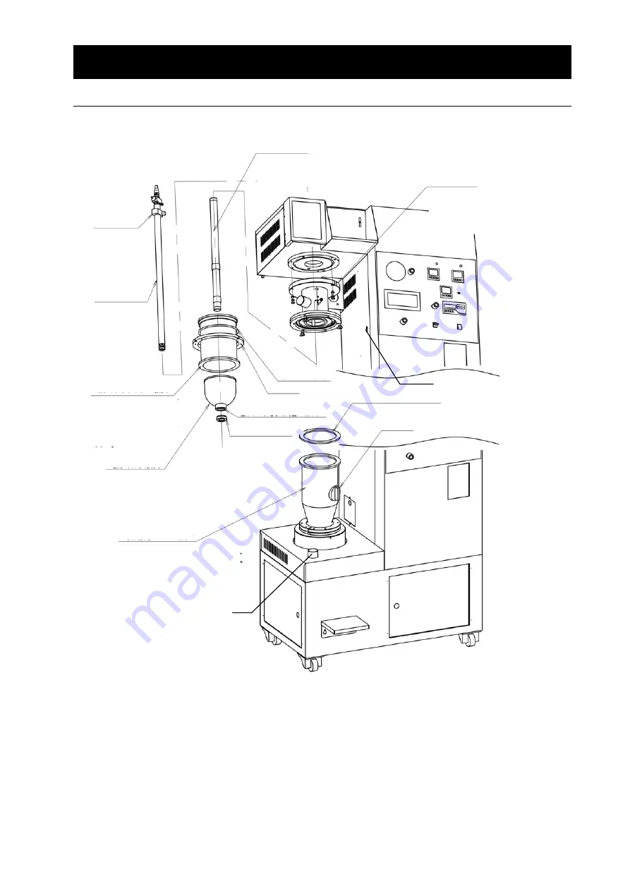
Install parts following the procedures in the order of their numbers.
(
4
)
Turn the POWER switch ON and raise the stage with UP of the lift switch. Stop moving the stage
once when the upper part of the flow layer chamber is close to the flange of the filter chamber,
and then turn the UP switch ON intermittently until the top flange of the flow layer chamber is
aligned with the packing and the flange of the filter chamber and the stage is stopped.
(
5
)
Install the temperature sensor to the pipe of the interim pipe and insert the plug into the socket
on the side of the main body.
(
6
)
Install the suction hose to the pipe of the interim pipe and the pipe at the left front of the stage
and fix them with hose clips.
温度センサ取付用ソケット
吸気ホース接続口
2. Installing the pipe
Fix this to an appropriate
position with a knurled
screw.
Nozzle fixing clamp
Install the interim pipe at three positions with M6 x
30 hex bolts (with flat washers and spring washer).
Top surface of interim pipe: with O ring P16
Groove on bottom surface of interim pipe: with O
ring P135
Upper inside of interim pipe: with O ring P30
1. Installing the interim pipe
3. Inserting the nozzle
2. Installing the pipe
Insert the pipe into the interim pipe and twist it
to the internal thread until it completely stops.
Take care for top and bottom directions.
4. Installing the filter chamber
Insert the nozzle from
the insert hole at the top
of the body.
Put the filter from under the filter
chamber through the pipe and push it
against the bottom surface of the interim
pipe. Screw it into the bottom end of the
filter retainer nut pipe, and push it up so
that the filter contacts with the interim
pipe without any gaps.
Hold the chamber with its stepped
flange up, install an O ring to the
stepped part, hook the butterfly nut on
the interim pipe to the groove on the
flange to fix.
5. Installing the filter
6. Installing the flow layer chamber
Make sure that on O ring is set in the stage, and
set the chamber so that two pins are aligned with
the grooves correctly. The cap will be the near
side.
O ring P145
Flange
O ring P30 (installed inside)
Filter retainer nut
Silicon packing (t5mm)
Cap
Temperature sensor socket
Suction hose connection port
Содержание PULVIS MINI BED GB210B
Страница 39: ...37 8 When a trouble occurs Confirmation of GB210A manual and language selection display ...
Страница 40: ...38 8 When a trouble occurs Confirmation of GB210A manual and language selection display ...
Страница 41: ...39 8 When a trouble occurs Confirmation of GB210B manual and language selection display ...
Страница 42: ...40 8 When a trouble occurs Confirmation of GB210B manual and language selection display ...


