2 - 44
SPEC
Ñ
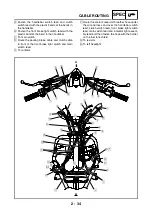
Secure the plastic band by inserting the projec-
tion on the band into the hole in the frame.
Ò
Fasten the wire harness with the plastic band so
that the ECU lead is routed downward.
Ó
Route the starter motor lead between the frame
and the battery box, then under the crankcase
breather hose.
Ô
Make sure that there is not excessive slack in
the wire sub lead in the area shown in the illus-
tration.
Õ
Route the wire sub lead as shown in the illustra-
tion. The longer lead past the end of the protec-
tive sleeve is the neutral switch lead and the
shorter lead is the reverse switch lead.
Ö
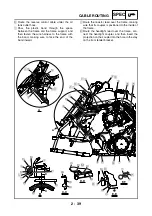
Route the A.C. magneto lead, negative battery
lead, wire sub lead, rear brake light switch lead,
and speed sensor lead between the crankcase
breather hose and the starter motor lead, and to
the rear of the leads that branch off from the wire
harness.
E
E
E
F
F
F
I
D
D
1
3
B
D
B
D
A-A
C-C
E-E
F-F
E
E
C
C
F
F
A
A
C
J
8
9
9
8
2
1
H
G
E
F
C
B
D
A
0
9
5
4
3
Ú
Õ
Ö
È
É
Ê
Ë
Ò
Ó
Ô
ÑÐ
Ï
Í
Î
8
7
6
Ù
Ø
×
Ì
Содержание YFM700RV 2006
Страница 1: ...YFM700RV SERVICE MANUAL 1S3 28197 E0 ...
Страница 34: ...2 11 SPEC ENGINE SPECIFICATIONS Cylinder head tightening sequence 1 3 2 4 5 7 8 6 ...
Страница 52: ...2 29 SPEC OIL FLOW DIAGRAMS 1 Oil delivery pipe 2 Oil filter 3 Oil pump 2 3 A A A A 2 1 ...
Страница 55: ...2 32 SPEC OIL FLOW DIAGRAMS 1 Balancer 1 2 Crankshaft 2 1 ...
Страница 408: ...YAMAHA MOTOR CO LTD 2500 SHINGAI IWATA SHIZUOKA JAPAN ...


