2 - 49
SPEC
1
Radiator fan motor relay
2
Headlight relay
3
Fuse box
4
Relay unit
5
Relay unit lead
6
Self-diagnosis signal lead
7
Starter motor lead
8
Starter relay lead
9
Starter relay
0
Fuse box lead
A
Headlight relay lead
B
Radiator fan motor relay lead
C
Tail/brake light lead
È
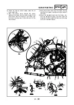
Route the starter motor lead under the starter
relay lead.
É
Make sure that the self-diagnosis signal coupler
is positioned above the relay unit lead, fuse box
lead, headlight relay lead, and radiator fan motor
relay lead.
Ê
Install the headlight relay, then the radiator fan
motor relay, onto the tab on the rear fender. The
headlight relay is identified by the presence of
white tape wrapped around its lead.
A-A
B-B
B
B
A
A
4
6
5
0
A
B
C
1
2
B
9
8
7
6
5
4
3
2
1
É
È
Ê
Содержание YFM700RV 2006
Страница 1: ...YFM700RV SERVICE MANUAL 1S3 28197 E0 ...
Страница 34: ...2 11 SPEC ENGINE SPECIFICATIONS Cylinder head tightening sequence 1 3 2 4 5 7 8 6 ...
Страница 52: ...2 29 SPEC OIL FLOW DIAGRAMS 1 Oil delivery pipe 2 Oil filter 3 Oil pump 2 3 A A A A 2 1 ...
Страница 55: ...2 32 SPEC OIL FLOW DIAGRAMS 1 Balancer 1 2 Crankshaft 2 1 ...
Страница 408: ...YAMAHA MOTOR CO LTD 2500 SHINGAI IWATA SHIZUOKA JAPAN ...


