4 - 66
ENG
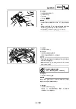
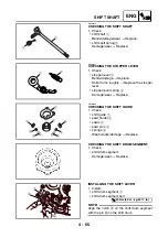
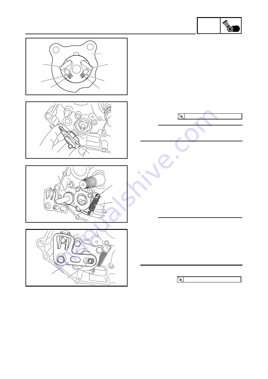
2. Install:
• springs
1
• pawl pins
2
• pawls
3
• shift guide
4
(to the pawl holder)
4
3
3
2
2
1
1
3. Install:
• shift lever assembly
1
• shift guide
2
NOTE:
The shift lever assembly is installed at the
same time as the shift guide.
1
2
T
R
.
.
10 Nm (1.0 m · kg, 7.2 ft · lb)
EBS00343
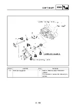
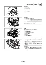
INSTALLING THE SHIFT SHAFT
1. Install:
• stopper lever
1
• stopper lever spring
2
• shift shaft
3
• roller
4
• shift shaft spring
NOTE:
• Hook the ends of the stopper lever spring
onto the stopper lever and the crankcase
boss
5
.
• Install the end of the shift shaft spring onto
the shift shaft spring stopper
6
.
• Install the end of the shift shaft lever onto the
roller
4
.
2. Install:
• shift pedal
Refer to “ADJUSTING THE SHIFT PEDAL”
in chapter 3.
1
5
2
4
3
6
T
R
.
.
16 Nm (1.6 m · kg, 11 ft · lb)
Содержание YFM700RV 2006
Страница 1: ...YFM700RV SERVICE MANUAL 1S3 28197 E0 ...
Страница 34: ...2 11 SPEC ENGINE SPECIFICATIONS Cylinder head tightening sequence 1 3 2 4 5 7 8 6 ...
Страница 52: ...2 29 SPEC OIL FLOW DIAGRAMS 1 Oil delivery pipe 2 Oil filter 3 Oil pump 2 3 A A A A 2 1 ...
Страница 55: ...2 32 SPEC OIL FLOW DIAGRAMS 1 Balancer 1 2 Crankshaft 2 1 ...
Страница 408: ...YAMAHA MOTOR CO LTD 2500 SHINGAI IWATA SHIZUOKA JAPAN ...


