UW10 Owner’s Manua
l
11
English
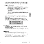
In this case, the INPUT and DIGITAL
IN jacks are disabled.
With some application programs, input
audio signals may be output unmodified. In
this case, do not set the SOURCE SELECT
switch to “TRACK DOWN.” Otherwise,
audio signals may oscillate, causing hearing
loss or damage to the playback device.
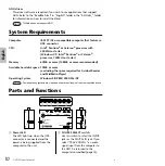
3
USB connector
Connect this connector to a
computer’s USB connector using a
USB cable.
You do not have to turn off the
power to the computer when you
connect this connector.
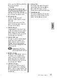
4
DIGITAL IN jack
A digital signal is input here from
an MD or CD player via an optical
digital cable (with square plugs).
Set the SOURCE SELECT switch on
the side panel to “DIGITAL.”
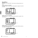
5
DIGITAL OUT jack
This jack is used to record a digital
signal from the computer to a
digital recorder, such as an MD
recorder. Use an optical digital
cable (with square plugs) to make
the connection.
Signals input at INPUT and
DIGITAL IN cannot be routed
directly to the DIGITAL OUT jack.
6
INPUT L/R jacks
Connect an audio device, such as a
CD player, here using RCA pin
cables. You can record an audio
signal input here to a computer.
Set the SOURCE SELECT switch on
the side panel to “INPUT.”
7
OUTPUT L/R jacks
These jacks are used to connect
powered speakers or a recording
device, such as a tape recorder. Use
RCA pin-plug cables for the L and R
connections.
8
Volume Dial
The Volume Dial adjusts the level of
signals output from the headphone
jack and OUTPUT jacks. Use the
Volume Dial to adjust the output level.
9
Headphone jack
Connect a headphone stereo mini-
plug here. Use the Volume Dial to
adjust the headphone volume.
CAUTION
NOTE
9

