


8-48
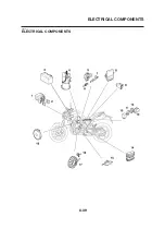
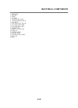
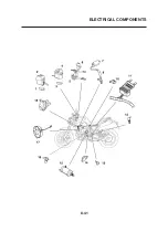
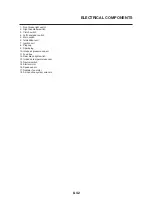
ELECTRICAL COMPONENTS
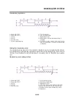
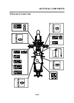
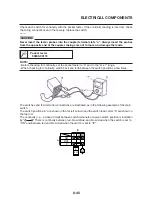
Immobilizer system indicator LED
Connect the pocket tester (kΩ x 1) to the
meter coupler.
Positive tester probe
→
black/white
Continuity
Negative tester probe
→
green/blue
Positive tester probe
→
green/blue
No continuity
Negative tester probe
→
black/white
WARNING
•
A wire that is used as a jumper lead must
have at least the same capacity of the bat-
tery lead, otherwise the jumper lead may
burn.
•
This check is likely to produce sparks,
therefore, make sure no flammable gas or
fluid is in the vicinity.
CAUTION:
Do not connect the jumper lead (battery
voltage) to the terminals (green/blue and
black/white) for the immobilizer system
indicator light (LED). The LED could be
damaged.
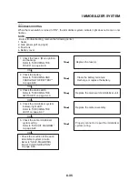
c. When the jumper leads are connected to the
terminals, the respective LED should illumi-
nate.
Does not light
→
Replace the meter assem-
bly.
▼▼▼▼▼▼▼▼▼▼▼▼▼▼▼▼▼▼▼▼▼▼▼▼▼▼▼▼▼▼▼▼
The following procedure applies to all of the
fuses.
To avoid a short circuit, always turn the
main switch to “OFF” when checking or
replacing a fuse.
1. Remove:
• Seats
• Fuel tank
Refer to “FUEL INJECTION SYSTEM” on
page 7-1.
2. Check:
• Fuse
▼▼▼▼▼▼▼▼▼▼▼▼▼▼▼▼▼▼▼▼▼▼▼▼▼▼▼▼▼▼▼▼
a. Connect the pocket tester to the fuse and
check the continuity.
NOTE:
Set the pocket tester selector to “Ω x 1”.
b. If the pocket tester indicates “∞”, replace the
fuse.
3. Replace:
• Blown fuse
a. Turn the main switch to “OFF”.
b. Install a new fuse of the correct amperage
rating.
c. Set on the switches to verify if the electrical
circuit is operational.
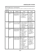
d. If the fuse immediately blows again, check
the electrical circuit.
Pocket tester
90890-03112
▼▼▼▼▼▼▼▼▼▼▼▼▼▼▼▼▼▼▼▼▼▼▼▼▼▼▼▼▼▼▼▼
▼▼▼▼▼▼▼▼▼▼▼▼▼▼▼▼▼▼▼▼▼▼▼▼▼▼▼▼▼▼▼▼
Fuses Amperage
Q’ty
rating
Main 30
A
1
Ignition 10
A
1
Headlight 20
A
1
Fuel injection system
10 A
1
Radiator fan motor
7.5 A
1
Signaling system
10 A
1
Parking lighting
10 A
1
Backup (odometer,
clock and immobilizer
10 A
1
system)
Spare 30
A
1
Spare 20
A
1
Spare 10
A
1
Spare
7.5 A
1
Содержание MT-03
Страница 7: ......
Страница 9: ......
Страница 25: ......
Страница 51: ...2 26 COOLING SYSTEM DIAGRAMS EAS00033 COOLING SYSTEM DIAGRAMS 5VK 5VK00 A 4 A B 4 3 2 1 2 3 1 A A A ...
Страница 53: ...2 28 COOLING SYSTEM DIAGRAMS 1 2 3 4 5 6 7 8 9 5 10 11 A B C ...
Страница 56: ...2 31 LUBRICATION CHART Pressure feed Splashed scavenge ...
Страница 57: ...2 32 LUBRICATION DIAGRAMS LUBRICATION DIAGRAMS A A 1 3 2 2 4 A A A A ...
Страница 58: ...2 33 LUBRICATION DIAGRAMS 1 Oil delivery hose 2 2 Oil strainer 3 Oil delivery hose 1 4 Oil tank ...
Страница 59: ...2 34 LUBRICATION DIAGRAMS A A A A 3 1 2 3 4 ...
Страница 60: ...2 35 LUBRICATION DIAGRAMS 1 Oil delivery pipe 2 2 Oil delivery pipe 1 3 Oil filter 4 Oil pump ...
Страница 61: ...2 36 LUBRICATION DIAGRAMS 1 7 2 3 4 5 6 A ...
Страница 63: ...2 38 LUBRICATION DIAGRAMS 1 6 5 4 3 2 ...
Страница 64: ...2 39 LUBRICATION DIAGRAMS 1 Camshaft 2 Oil delivery pipe 1 3 Oil filter 4 Main axle 5 Drive axle 6 Crankshaft ...
Страница 65: ...2 40 CABLE ROUTING CABLE ROUTING ...
Страница 67: ...2 42 CABLE ROUTING ...
Страница 69: ...2 44 CABLE ROUTING ...
Страница 71: ...2 46 CABLE ROUTING ...
Страница 73: ...2 48 CABLE ROUTING ...
Страница 75: ...2 50 CABLE ROUTING ...
Страница 77: ...2 52 CABLE ROUTING ...
Страница 79: ...2 54 CABLE ROUTING ...
Страница 81: ...2 56 CABLE ROUTING ...
Страница 83: ...2 58 CABLE ROUTING ...
Страница 85: ...2 60 CABLE ROUTING ...
Страница 87: ......
Страница 121: ......
Страница 177: ...4 54 FRONT FORK WARNING Make sure the brake hoses are routed prop erly ...
Страница 271: ......
Страница 273: ......
Страница 287: ......
Страница 325: ......
Страница 339: ...8 12 CHARGING SYSTEM 2 A C magneto 5 Rectifier regulator 7 Battery 8 Main fuse ...
Страница 341: ...8 14 CHARGING SYSTEM ...
Страница 355: ...8 28 COOLING SYSTEM ...
Страница 365: ...8 38 IMMOBILIZER SYSTEM ...
Страница 366: ...8 39 ELECTRICAL COMPONENTS EAS27970 ELECTRICAL COMPONENTS ...
Страница 368: ...8 41 ELECTRICAL COMPONENTS ...
Страница 370: ...8 43 ELECTRICAL COMPONENTS EAS27980 CHECKING THE SWITCHES ...
Страница 389: ......
Страница 391: ......
Страница 397: ...COLOR CODE ...
Страница 398: ......
Страница 399: ...YAMAHA MOTOR ITALIA S P A ...
Страница 400: ...MT 03 2006 WIRING DIAGRAM ...


