


8-31
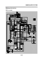
IMMOBILIZER SYSTEM
EAS27670
GENERAL INFORMATION
This vehicle is equipped with an immobilizer system to help prevent theft by re-registering codes in
the standard keys. This system consists of the following:
• a code re-registering key (with a red bow)
• two standard keys (with a black bow) that can be re-registered with new codes
• a transponder (installed in the red key bow)
• an immobilizer unit
• the ECU
• an immobilizer system indicator light
The key with the red bow is used to register codes in each standard key. Do not use the key with the
red bow for driving. It should only be used for re-registering new codes in the standard keys. The im-
mobilizer system cannot be operated with a new key until the key registered with a code. If you lose
the code re-registering key, the ECU and main switch (equipped with the immobilizer unit) need to
be replaced.
Therefore, always use a standard key for driving. (See caution below.)
NOTE:
Each standard key is registered during production, therefore re-registering at purchase is not neces-
sary.
EC5YU1026
CAUTION:
• DO NOT LOSE THE CODE RE-REGISTERING KEY! If the code re-registering key is lost,
regis-tering new codes in the standard keys is impossible. The standard keys can still be
used to start the vehicle. However, if code re-registering is required (e.g., if a new standard
key is made or all keys are lost) the entire immobilizer system must be replaced. Therefore,
it is highly recommended to use either standard key for driving, and to keep the code re-
registering key in a safe place.
• Do not submerse the keys in water.
• Do not expose the keys to excessively high temperatures.
• Do not place the keys close to magnets (this includes, but is not limited to, products such
as speakers, etc.).
• Do not place heavy items on the keys.
• Do not grind the keys or alter their shape.
• Do not disassemble the key bows.
• Do not put two keys of any immobilizer system on the same key ring.
• Keep the standard keys as well as other immobilizer system keys away from the code re-
registering key.
• Keep other immobilizer system keys away from the main switch as they may cause signal
interference.
Содержание MT-03
Страница 7: ......
Страница 9: ......
Страница 25: ......
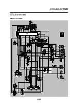
Страница 51: ...2 26 COOLING SYSTEM DIAGRAMS EAS00033 COOLING SYSTEM DIAGRAMS 5VK 5VK00 A 4 A B 4 3 2 1 2 3 1 A A A ...
Страница 53: ...2 28 COOLING SYSTEM DIAGRAMS 1 2 3 4 5 6 7 8 9 5 10 11 A B C ...
Страница 56: ...2 31 LUBRICATION CHART Pressure feed Splashed scavenge ...
Страница 57: ...2 32 LUBRICATION DIAGRAMS LUBRICATION DIAGRAMS A A 1 3 2 2 4 A A A A ...
Страница 58: ...2 33 LUBRICATION DIAGRAMS 1 Oil delivery hose 2 2 Oil strainer 3 Oil delivery hose 1 4 Oil tank ...
Страница 59: ...2 34 LUBRICATION DIAGRAMS A A A A 3 1 2 3 4 ...
Страница 60: ...2 35 LUBRICATION DIAGRAMS 1 Oil delivery pipe 2 2 Oil delivery pipe 1 3 Oil filter 4 Oil pump ...
Страница 61: ...2 36 LUBRICATION DIAGRAMS 1 7 2 3 4 5 6 A ...
Страница 63: ...2 38 LUBRICATION DIAGRAMS 1 6 5 4 3 2 ...
Страница 64: ...2 39 LUBRICATION DIAGRAMS 1 Camshaft 2 Oil delivery pipe 1 3 Oil filter 4 Main axle 5 Drive axle 6 Crankshaft ...
Страница 65: ...2 40 CABLE ROUTING CABLE ROUTING ...
Страница 67: ...2 42 CABLE ROUTING ...
Страница 69: ...2 44 CABLE ROUTING ...
Страница 71: ...2 46 CABLE ROUTING ...
Страница 73: ...2 48 CABLE ROUTING ...
Страница 75: ...2 50 CABLE ROUTING ...
Страница 77: ...2 52 CABLE ROUTING ...
Страница 79: ...2 54 CABLE ROUTING ...
Страница 81: ...2 56 CABLE ROUTING ...
Страница 83: ...2 58 CABLE ROUTING ...
Страница 85: ...2 60 CABLE ROUTING ...
Страница 87: ......
Страница 121: ......
Страница 177: ...4 54 FRONT FORK WARNING Make sure the brake hoses are routed prop erly ...
Страница 271: ......
Страница 273: ......
Страница 287: ......
Страница 325: ......
Страница 339: ...8 12 CHARGING SYSTEM 2 A C magneto 5 Rectifier regulator 7 Battery 8 Main fuse ...
Страница 341: ...8 14 CHARGING SYSTEM ...
Страница 355: ...8 28 COOLING SYSTEM ...
Страница 365: ...8 38 IMMOBILIZER SYSTEM ...
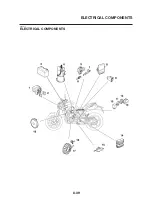
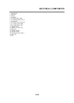
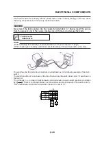
Страница 366: ...8 39 ELECTRICAL COMPONENTS EAS27970 ELECTRICAL COMPONENTS ...
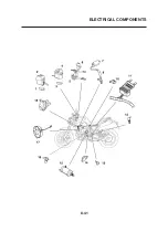
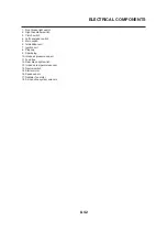
Страница 368: ...8 41 ELECTRICAL COMPONENTS ...
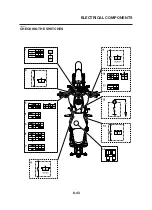
Страница 370: ...8 43 ELECTRICAL COMPONENTS EAS27980 CHECKING THE SWITCHES ...
Страница 389: ......
Страница 391: ......
Страница 397: ...COLOR CODE ...
Страница 398: ......
Страница 399: ...YAMAHA MOTOR ITALIA S P A ...
Страница 400: ...MT 03 2006 WIRING DIAGRAM ...


