


4-68
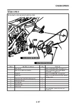
CHAIN DRIVE
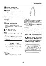
1. Stand the vehicle on a level surface.
Securely support the vehicle so that there is
no danger of it falling over.
Place the vehicle on a suitable stand so that
the rear wheel is elevated.
• 15-link section “a” of the drive chain
• While measuring the 15-link section, push
down on the drive chain to increase its ten-
sion.
• Measure the length between drive chain roller
• Perform this measurement at two or three dif-
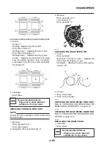
Clean and lubricate or replace.
3. Clean:
• Drive chain
▼▼▼▼▼▼▼▼▼▼▼▼▼▼▼▼▼▼▼▼▼▼▼▼▼▼▼▼▼▼▼▼
a. Wipe the drive chain with a clean cloth.
b. Put the drive chain in kerosene and remove
any remaining dirt.
c. Remove the drive chain from the kerosene
and completely dry it.
EC5YU1022
CAUTION:
•
This vehicle has a drive chain with small
rubber O-rings “1” between the drive chain
side plates. Never use high-pressure water
or air, steam, gasoline, certain solvents
(e.g., benzine), or a coarse brush to clean
the drive chain. High-pressure methods
could force dirt or water into the drive
chain’s internals, and solvents will deterio-
rate the O-rings. A coarse brush can also
damage the O-rings. Therefore, use only
kerosene to clean the drive chain.
•
Do not soak the drive chain in kerosene for
more than ten minutes, otherwise the O-
rings can be damaged.
Содержание MT-03
Страница 7: ......
Страница 9: ......
Страница 25: ......
Страница 51: ...2 26 COOLING SYSTEM DIAGRAMS EAS00033 COOLING SYSTEM DIAGRAMS 5VK 5VK00 A 4 A B 4 3 2 1 2 3 1 A A A ...
Страница 53: ...2 28 COOLING SYSTEM DIAGRAMS 1 2 3 4 5 6 7 8 9 5 10 11 A B C ...
Страница 56: ...2 31 LUBRICATION CHART Pressure feed Splashed scavenge ...
Страница 57: ...2 32 LUBRICATION DIAGRAMS LUBRICATION DIAGRAMS A A 1 3 2 2 4 A A A A ...
Страница 58: ...2 33 LUBRICATION DIAGRAMS 1 Oil delivery hose 2 2 Oil strainer 3 Oil delivery hose 1 4 Oil tank ...
Страница 59: ...2 34 LUBRICATION DIAGRAMS A A A A 3 1 2 3 4 ...
Страница 60: ...2 35 LUBRICATION DIAGRAMS 1 Oil delivery pipe 2 2 Oil delivery pipe 1 3 Oil filter 4 Oil pump ...
Страница 61: ...2 36 LUBRICATION DIAGRAMS 1 7 2 3 4 5 6 A ...
Страница 63: ...2 38 LUBRICATION DIAGRAMS 1 6 5 4 3 2 ...
Страница 64: ...2 39 LUBRICATION DIAGRAMS 1 Camshaft 2 Oil delivery pipe 1 3 Oil filter 4 Main axle 5 Drive axle 6 Crankshaft ...
Страница 65: ...2 40 CABLE ROUTING CABLE ROUTING ...
Страница 67: ...2 42 CABLE ROUTING ...
Страница 69: ...2 44 CABLE ROUTING ...
Страница 71: ...2 46 CABLE ROUTING ...
Страница 73: ...2 48 CABLE ROUTING ...
Страница 75: ...2 50 CABLE ROUTING ...
Страница 77: ...2 52 CABLE ROUTING ...
Страница 79: ...2 54 CABLE ROUTING ...
Страница 81: ...2 56 CABLE ROUTING ...
Страница 83: ...2 58 CABLE ROUTING ...
Страница 85: ...2 60 CABLE ROUTING ...
Страница 87: ......
Страница 121: ......
Страница 177: ...4 54 FRONT FORK WARNING Make sure the brake hoses are routed prop erly ...
Страница 271: ......
Страница 273: ......
Страница 287: ......
Страница 325: ......
Страница 339: ...8 12 CHARGING SYSTEM 2 A C magneto 5 Rectifier regulator 7 Battery 8 Main fuse ...
Страница 341: ...8 14 CHARGING SYSTEM ...
Страница 355: ...8 28 COOLING SYSTEM ...
Страница 365: ...8 38 IMMOBILIZER SYSTEM ...
Страница 366: ...8 39 ELECTRICAL COMPONENTS EAS27970 ELECTRICAL COMPONENTS ...
Страница 368: ...8 41 ELECTRICAL COMPONENTS ...
Страница 370: ...8 43 ELECTRICAL COMPONENTS EAS27980 CHECKING THE SWITCHES ...
Страница 389: ......
Страница 391: ......
Страница 397: ...COLOR CODE ...
Страница 398: ......
Страница 399: ...YAMAHA MOTOR ITALIA S P A ...
Страница 400: ...MT 03 2006 WIRING DIAGRAM ...