


1-3
FEATURES
EAS00897
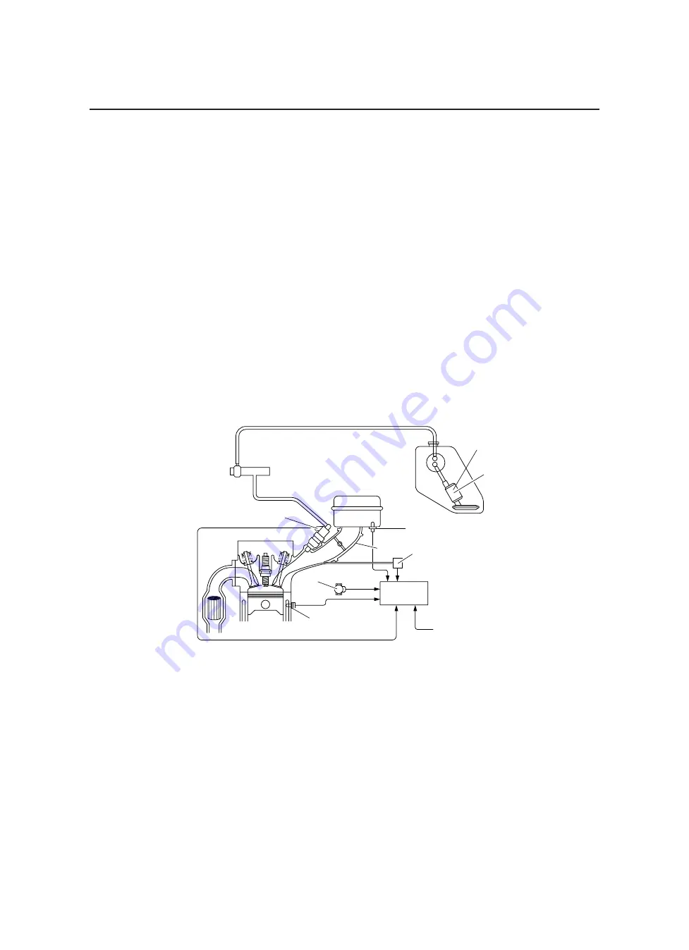
FI SYSTEM
The fuel pump delivers fuel to the injector via the fuel filter. The pressure regulator maintains the fu-
el pressure that is applied to the injector at 324 kPa (3.24 kg/cm
2
, 46.1 psi) higher than the intake
manifold pressure. Accordingly, when the energizing signal from the ECU energizes the injector, the
fuel passage opens, causing the fuel to be injected into the intake manifold only during the time the
passage remains open. Therefore, the longer the length of time the injector is energized (injection
duration), the greater the volume of fuel that is supplied. Conversely, the shorter the length of time
the injector is energized (injection duration), the lesser the volume of fuel that is supplied.
The injection duration and the injection timing are controlled by the ECU. Signals that are input from
the throttle position sensor, crankshaft position sensor, intake air pressure sensor, intake air temper-
ature sensor, and coolant temperature sensor enable the ECU to determine the injection duration.
The injection timing is determined through the signal from the crankshaft position sensor. As a result,
the volume of fuel that is required by the engine can be supplied at all times in accordance with the
driving conditions.
Illustration is for reference only.
1. Fuel
pump
2. Pressure
regulator
3. Fuel
injector
4. Throttle
body
5. Intake air temperature sensor
6. Throttle position sensor
7. Intake air pressure sensor
8. ECU
9. Coolant temperature sensor
10. Crankshaft position sensor
A. Fuel
system
B. Air
system
C. Control system
2
1
5
4
8
7
6
9
#
3
1
A
B
C
10
Содержание MT-03
Страница 7: ......
Страница 9: ......
Страница 25: ......
Страница 51: ...2 26 COOLING SYSTEM DIAGRAMS EAS00033 COOLING SYSTEM DIAGRAMS 5VK 5VK00 A 4 A B 4 3 2 1 2 3 1 A A A ...
Страница 53: ...2 28 COOLING SYSTEM DIAGRAMS 1 2 3 4 5 6 7 8 9 5 10 11 A B C ...
Страница 56: ...2 31 LUBRICATION CHART Pressure feed Splashed scavenge ...
Страница 57: ...2 32 LUBRICATION DIAGRAMS LUBRICATION DIAGRAMS A A 1 3 2 2 4 A A A A ...
Страница 58: ...2 33 LUBRICATION DIAGRAMS 1 Oil delivery hose 2 2 Oil strainer 3 Oil delivery hose 1 4 Oil tank ...
Страница 59: ...2 34 LUBRICATION DIAGRAMS A A A A 3 1 2 3 4 ...
Страница 60: ...2 35 LUBRICATION DIAGRAMS 1 Oil delivery pipe 2 2 Oil delivery pipe 1 3 Oil filter 4 Oil pump ...
Страница 61: ...2 36 LUBRICATION DIAGRAMS 1 7 2 3 4 5 6 A ...
Страница 63: ...2 38 LUBRICATION DIAGRAMS 1 6 5 4 3 2 ...
Страница 64: ...2 39 LUBRICATION DIAGRAMS 1 Camshaft 2 Oil delivery pipe 1 3 Oil filter 4 Main axle 5 Drive axle 6 Crankshaft ...
Страница 65: ...2 40 CABLE ROUTING CABLE ROUTING ...
Страница 67: ...2 42 CABLE ROUTING ...
Страница 69: ...2 44 CABLE ROUTING ...
Страница 71: ...2 46 CABLE ROUTING ...
Страница 73: ...2 48 CABLE ROUTING ...
Страница 75: ...2 50 CABLE ROUTING ...
Страница 77: ...2 52 CABLE ROUTING ...
Страница 79: ...2 54 CABLE ROUTING ...
Страница 81: ...2 56 CABLE ROUTING ...
Страница 83: ...2 58 CABLE ROUTING ...
Страница 85: ...2 60 CABLE ROUTING ...
Страница 87: ......
Страница 121: ......
Страница 177: ...4 54 FRONT FORK WARNING Make sure the brake hoses are routed prop erly ...
Страница 271: ......
Страница 273: ......
Страница 287: ......
Страница 325: ......
Страница 339: ...8 12 CHARGING SYSTEM 2 A C magneto 5 Rectifier regulator 7 Battery 8 Main fuse ...
Страница 341: ...8 14 CHARGING SYSTEM ...
Страница 355: ...8 28 COOLING SYSTEM ...
Страница 365: ...8 38 IMMOBILIZER SYSTEM ...
Страница 366: ...8 39 ELECTRICAL COMPONENTS EAS27970 ELECTRICAL COMPONENTS ...
Страница 368: ...8 41 ELECTRICAL COMPONENTS ...
Страница 370: ...8 43 ELECTRICAL COMPONENTS EAS27980 CHECKING THE SWITCHES ...
Страница 389: ......
Страница 391: ......
Страница 397: ...COLOR CODE ...
Страница 398: ......
Страница 399: ...YAMAHA MOTOR ITALIA S P A ...
Страница 400: ...MT 03 2006 WIRING DIAGRAM ...