47
MODX6/MODX7
LCD display
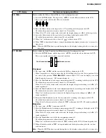
Test items and judging conditions
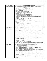
24 : Factory Set
Sets to the factory default data. (It takes about 8 seconds.)
After writing the initial value of each parameter in the SDRAM, those data is written to the eMMC
(IC403).
Caution
Note that all user data will be cleared. Before executing the factory reset procedure, be sure to save the
important data as a backup in the USB flash drive. (See page 77.)
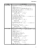
1) Press the [ENTER] button, and then the result is shown on the LCD.
When the test result is OK, a sine wave sound is produced momentarily.
Until the result is given, “Now Executing...” is shown.
If no problem is found:
OK
If any problem is found:
NG
2) Confirm that “
OK
” is shown on the LCD.
3) When OK/NG of the test result is shown, testing is finished and the display is changed to the test
item selection screen.
25 : Auto Power Off
Turn off the power with software. (After executing test items, the power of the main unit turns off.)
1) Press the [ENTER] button, and the power turns off automatically.
2) Turn on the power manually and confirm that the main unit starts up.
When NG of the test result is shown, testing is finished and the display is changed to the test item
selection screen.
Press the [EXIT] button to shift the display to the EXIT test selection screen.
26 : Exit
Exit the test mode and the power turns off.
1) Press the [ENTER] button, and “
[NO] or [YES]
” is shown on the LCD.
2) Press the [INC/YES] button, and then the power turns off.
3) Turn on the [STANDBY/ON] switch for restarting.
Confirm that the live set screen in the normal mode appears.
Note: Do not turn off the power until the live set screen appears.
27 : OUTPUT-L (0dB)
Checks each output level from the L channel of the jacks.
1) Connect the level meter to an output jack.
2) Set the [MASTER VOLUME] control to the maximum position.
3) Press the [ENTER] button to produce the 1kHz sine wave sound. “
ON
” is shown on the LCD.
4) Measure the output level and confirm that the measured values are within the specified range.
[OUTPUT]
(10k
-ohms
load)
L/MONO : +8.0 dBu±2 dB
5) Press the [EXIT] button, and testing is finished and the display is changed to the test item selection
screen.
28 : OUTPUT-R (0dB)
Checks each output level from the R channel of the jacks.
1) Connect the level meter to an output jack.
2) Set the [MASTER VOLUME] control to the maximum position.
3) Press the [ENTER] button to produce the 1kHz sine wave sound. “
ON
” is shown on the LCD.
4) Measure the output level and confirm that the measured values are within the specified range.
[OUTPUT]
(10k
-ohms
load)
R : +8.0 dBu±2 dB
5) Press the [EXIT] button, and testing is finished and the display is changed to the test item selection
screen.
Содержание MODX6
Страница 23: ...23 MODX6 MODX7 C C Pattern side DM Circuit Board C C 2NA ZW84620 1...
Страница 24: ...MODX6 MODX7 24 PNC Circuit Board Component side 2NA ZX42110...
Страница 28: ...MODX6 MODX7 28 PNR Circuit Board Component side 2NA ZX42110...
Страница 29: ...29 MODX6 MODX7 to PNC CB107 Pattern side PNR Circuit Board 2NA ZX42110...
Страница 31: ...31 MODX6 MODX7 TOME4 Circuit Board Component side Pattern side 2NA ZX42110...
Страница 32: ...MODX6 MODX7 32 2NAK8 V869520 1 61L Circuit Board Component side D D D D to 61H CN3 to KEY IF CB504...
Страница 35: ...35 MODX6 MODX7 76H Circuit Board 2NAK8 ZW58960 Component side to KEY IF CB508 to 76L CN3 G G G G H H H H...
Страница 73: ...73 MODX6 MODX7 3 Searching for the updater 4 Searching for the updater OK 5 Finish Please turn off 6 USB 7 8 22...
Страница 74: ...MODX6 MODX7 74 SYSTEM BOOTING FLOWCHART...
Страница 99: ...14 MODX6 MODX7 MODX6 KEYBOARD ASSEMBLY Ass y 120 120 220 100 151 152 100 10 10 30 50 50 60 85 90 80 20 40 40 20...

