45
MODX6/MODX7
LCD display
Test items and judging conditions
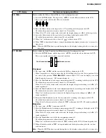
16 : A/D -> D/A (LINE)
Checks the signal path from the A/D input to D/A output. (Gain is set to LINE due to Default.)
1) Connect the level meter to [OUTPUT] jack.
(Connect the plug to both jacks of L/MONO and R.)
2) Set the [MASTER VOLUME] control to the maximum position.
3) Press the [ENTER] button.
4) Do not insert the plug to the A/D INPUT [R] jack.
5) Connect an oscillator to the A/D INPUT [L/MONO] jack.
6) Input a 1kHz, -14.8dBu sine wave.
7) Set the A/D INPUT [GAIN] knob to the maximum position.
8) Confirm that the input level L/R value is higher than “43”.
9) Measure the output level and confirm that the measured values are within the specified range.
[OUTPUT]
(10k
-ohms
load)
L/MONO :+1.6 dBu±2 dB
R : +1.6 dBu±2 dB
10) Set the A/D INPUT [GAIN] knob to the minimum position.
11) Confirm that the input level L/R value is lower than “4”.
12) Measure the output level and confirm that the measured values are within the specified range.
[OUTPUT]
(10k
-ohms
load)
L/MONO :-68.0 dBu or less
R : -68.0 dBu or less
13) “
OK
” is shown on the LCD.
14) Press the [EXIT] button, and testing is finished and the display is changed to the test item selection
screen.
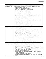
17 : MUTE (Analog)
Checks whether the MUTE for all outputs works properly or not.
1) Connect the level meter to an output jack.
2) Set the [MASTER VOLUME] control to the maximum position.
3) Press the [ENTER] button to produce the sine wave sound. “
OFF
” is shown on the LCD.
4) Press the [ENTER] button to activate the MUTE circuit.
“
ON
” is shown on the LCD, and all the output from the PHONES and OUTPUT jacks are muted.
5) Press the [ENTER] button to cancel the MUTE circuit.
“
OFF
” is shown on the LCD and the sound is produced.
6) Check the output level when the MUTE is at ON.
Measure the output level and confirm that the measured values are within the specified range.
[PHONES]
(33
-ohms
load)
PHONES L: -40.0 dBu or less PHONES R: -40.0 dBu or less
[OUTPUT]
(10k
-ohms
load)
L/MONO : -45.0 dBu or less R : -45.0 dBu or less
7) Press the [EXIT] button, and testing is finished and the display is changed to the test item selection
screen.
18 : MUTE (DAC)
Checks whether the DAC MUTE for the DAC IC’s output works properly or not.
1) Connect the level meter to an output jack.
2) Set the [MASTER VOLUME] control to the maximum position.
3) Press the [ENTER] button to produce the sine wave sound. “
OFF
” is shown on the LCD.
4) Press the [ENTER] button to activate the DAC MUTE circuit.
“
ON
” is shown on the LCD, and all the output from the PHONES and OUTPUT jacks are muted.
5) Press the [ENTER] button to cancel the DAC MUTE circuit.
“
OFF
” is shown on the LCD and the sound is produced.
6) Check the output level when the MUTE is at ON.
Measure the output level and confirm that the measured values are within the specified range.
[OUTPUT]
(10k
-ohms
load)
L/MONO : -80.0 dBu or less R : -80.0 dBu or less
7) Press the [EXIT] button, and testing is finished and the display is changed to the test item selection
screen.
Содержание MODX6
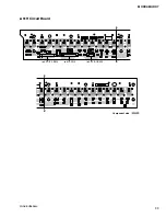
Страница 23: ...23 MODX6 MODX7 C C Pattern side DM Circuit Board C C 2NA ZW84620 1...
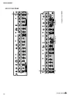
Страница 24: ...MODX6 MODX7 24 PNC Circuit Board Component side 2NA ZX42110...
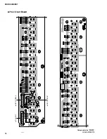
Страница 28: ...MODX6 MODX7 28 PNR Circuit Board Component side 2NA ZX42110...
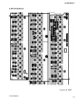
Страница 29: ...29 MODX6 MODX7 to PNC CB107 Pattern side PNR Circuit Board 2NA ZX42110...
Страница 31: ...31 MODX6 MODX7 TOME4 Circuit Board Component side Pattern side 2NA ZX42110...
Страница 32: ...MODX6 MODX7 32 2NAK8 V869520 1 61L Circuit Board Component side D D D D to 61H CN3 to KEY IF CB504...
Страница 35: ...35 MODX6 MODX7 76H Circuit Board 2NAK8 ZW58960 Component side to KEY IF CB508 to 76L CN3 G G G G H H H H...
Страница 73: ...73 MODX6 MODX7 3 Searching for the updater 4 Searching for the updater OK 5 Finish Please turn off 6 USB 7 8 22...
Страница 74: ...MODX6 MODX7 74 SYSTEM BOOTING FLOWCHART...
Страница 99: ...14 MODX6 MODX7 MODX6 KEYBOARD ASSEMBLY Ass y 120 120 220 100 151 152 100 10 10 30 50 50 60 85 90 80 20 40 40 20...


