background image

Sampling Mode [SAMPLING]

Reference

142

DTXTREME III Owner’s Manual

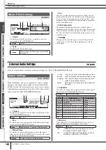
Sampling Jobs

[F4] JOB

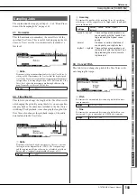
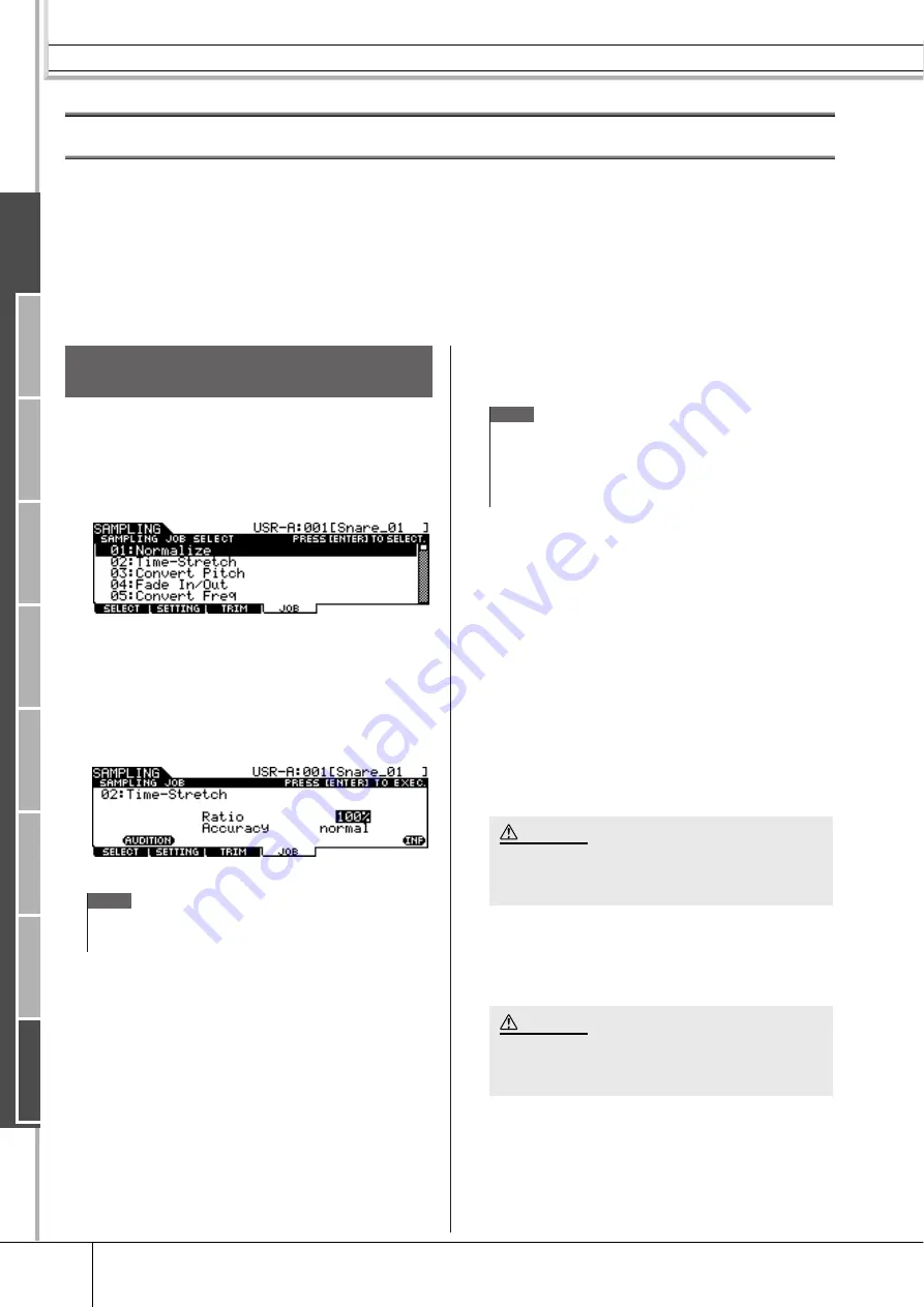
The Sampling Job lets you process and modify User Voices you have recorded. 14 Sampling Jobs are available. 

01: Normalize 

06: Stereo to Mono 

11: Delete

02: Time-Stretch 

07: Loop-Remix 

12: Delete All

03: Convert Pitch

08: Slice 

13: Extract

04: Fade In/Out 

09: Name 

14: Optimize Memory

05: Convert Freq 

10: Copy

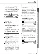
1

From the [F1] SELECT display, select the 
User Voice to which the Job is applied. 

2

Press the [F4] JOB button. 

3

Move the cursor to the desired Job by 
using the data dial, [INC/DEC] and [DEC/
NO] buttons or Cursor up/down buttons, 
then press the [ENTER/STORE] button. 

The selected Job display appears.

Press the [EXIT] button to go back to the Job menu display.

4

Move the cursor to the desired parameter, 
then set the value by using the data dial, 
[INC/YES] and [DEC/NO] buttons.

5

Press the [ENTER/STORE] button to exe-
cute the Job. 

If “Are you sure?” appears, go to Step 6. If not, go to step 7. 

6

Press the [INC/YES] button. 

To cancel the Job, press the [DEC/NO] button then go back to 
step 4. 

7

Press the [SF1] AUDITION button to hear 
the modified sound. 

At this time, the User Voice has been modified temporarily 
and is not fixed as data. 

8

Press the [F6] OK button if you are satis-
fied with the result of the Job operation. 

If you are not satisfied with the result of the Job operation, 
press the [F5] CANCEL button and go back to Step 4. 

9

Save the created User Voice data to a USB 
storage device. 

For detailed instructions on saving, see pages 55 and 114.

Basic Procedure of the Sampling 
Jobs

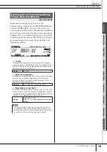
NOTE

• When the User Voice contains no audio data, pressing the [ENTER/

STORE] button cannot call up the Job display, depending on the 
selected Job. 

NOTE

• When executing the “08: Slice” Job, you will need to set additional 

parameters: Select and Save To. Set these parameters, press the 
[ENTER/STORE] button, then press the [INC/YES] button to assign 
the sliced audio data to the specified User Voice. Repeat this proce-
dure as desired (depending on the Subdivide setting) then go to Step 
9. 

• You cannot return the modified User Voice to the original after fix-

ing the Job result. Important data should always be saved to a 
USB storage device connected to the USB TO DEVICE terminal 
(pages 55 and 114). 

• The recorded audio data resides temporarily in DIMM (pages 76 

and 147). Any data in DIMM will be lost when turning the power 
off. You should always save any data residing in DIMM to a USB 
storage device before turning off the power. 

CAUTION

CAUTION

Ref

erence

Dr
um Kit mode

Song mode

Clic

k mode

Tr

igger mode

File mode

Utility mode

Chain mode

Sampling mode


Содержание DTXTREME III

Страница 1: ...EN OWNER S MANUAL ...

Страница 2: ...to how a function or effect works when the unit is operating as designed are not covered by the manufacturer s warranty and are therefore the owners responsibility Please study this manual carefully and consult your dealer before requesting service ENVIRONMENTAL ISSUES Yamaha strives to produce products that are both user safe and environ mentally friendly We sincerely believe that our products an...

Страница 3: ...erence Utilize power outlets that are on different branch circuit breaker or fuse circuits or install AC line filter s In the case of radio or TV interference relocate reorient the antenna If the antenna lead in is 300 ohm ribbon lead change the lead in to co axial type cable If these corrective measures do not produce satisfactory results please contact the local retailer authorized to distribute...

Страница 4: ...h disconnect the adaptor plug from the outlet and have the instrument inspected by qualified Yamaha service personnel CAUTION Always follow the basic precautions listed below to avoid the possibility of physical injury to you or others or damage to the instrument or other property These precautions include but are not limited to the following When removing the electric plug from the instrument or ...

Страница 5: ... data in the Flash ROM This means that this instrument may not be able to start up properly even when turning the power on next time Saving factory preset data When you save your original data to flash ROM the factory preset data in some area of the flash ROM will be lost Before saving your original data be sure to save the factory preset data to external USB storage device Backing up the external...

Страница 6: ...s Manual and the copyrights thereof are under exclusive ownership by Yamaha Corporation The illustrations and LCD screens as shown in this owner s manual are for instructional purposes only and may appear somewhat different from those on your instrument This product incorporates and bundles computer programs and contents in which Yamaha owns copyrights or with respect to which it has license to us...

Страница 7: ...n be assigned to the Drum Kit as desired The instrument is equipped with a Variation Effect which can be used for each Drum Kit as well as Reverb Chorus and Master Effects which can be used for the entire DTX TREME III In addition an Insertion Effect for the sound input via the AUX IN SAMPLING IN jack is provided allowing you to adjust the quality of AUX IN SAMPLING IN sound or record an audio sig...

Страница 8: ...a Track After Clearing 48 Assigning a Name to a User Song 49 Using the Groove Check Function 50 Setting the Check Timing 50 Trying Out Groove Check 51 Trying Out Rhythm Gate 52 Saving the Created Data to a USB Storage Device 54 File Folder Selection 54 Saving the Created Data to a USB Storage Device 55 Loading a File Saved to a USB Storage Device 56 Reference 57 Basic Structure of the DTXTREME III...

Страница 9: ...GENERAL 124 Pad Settings F2 PAD 126 Effect Settings F3 EFFECT 127 External Audio Settings F4 AUXIN 128 MIDI Settings F5 MIDI 130 Resetting the User Memory to the Initial Factory Settings F6 FACTSET 131 Chain Mode CHAIN 132 Using a Programmed Chain F1 SELECT 132 Programming a Chain F2 EDIT 133 Naming the created Chain F3 NAME 134 Sampling Mode SAMPLING 135 Sampling Setup 135 Sampling Operation and ...

Страница 10: ...s 54 and 112 y CHAIN button Pressing this button enters the Chain mode allowing you to program a Chain which is a series of Drum Kits and Songs arranged in the order you want page 132 u SONG button Pressing this button enters the Song mode allowing you to play an existing Song or record your drum performance pages 35 and 98 i TRIGGER button Pressing this button enters the Trigger mode allowing you...

Страница 11: ...sts the output volume of the stereo mix from the OUTPUT L MONO and R jacks 7 PHONES slider page 31 Adjusts the output volume of the stereo mixed sounds for the PHONES jack This is independent from the MASTER slider setting 8 CLICK slider page 31 Adjusts the output volume of the click sound 9 ACCOMP slider page 31 Adjusts the output volume of the accompaniment parts those other than MIDI channel 10...

Страница 12: ... slider set ting the digital jack always outputs audio signals at the maxi mum volume level 1 MIDI IN OUT connectors These jacks are for the transfer of MIDI data to and from exter nal MIDI devices 2 USB terminals This instrument is equipped with two types of USB terminals on the rear panel USB TO HOST and USB TO DEVICE The USB TO HOST terminal is used to connect this instrument to the computer vi...

Страница 13: ...displays with various functions and parameters To navigate your way through these displays and select a desired function use the F1 F6 buttons and the SF1 SF6 buttons When you select a mode the available displays or menus appear directly above the buttons at the bottom of the display as shown below Depending on the currently selected mode up to six func tions are available and can be called up wit...

Страница 14: ...meter the NUM icon appears at the lower right corner of the LCD display When the SF6 NUM but ton is pressed in this status each digit 1 9 0 is assigned to the SF1 SF5 and F1 F5 buttons as shown below allowing you to input a number directly by using these buttons After completing the number input press the ENTER STORE button to actually enter the number Note that the cursor highlight can be moved t...

Страница 15: ...e method you may want to use the following method selecting the characters directly from a list Inputting Characters Naming etc Move the cursor to the desired location in the name Select a character at the cursor location When the cursor is located at the Name this LIST icon appears and you can call up the Character List display by holding the SF6 button Release the SF6 button to return back to th...

Страница 16: ...ing any connections to the DTXTREME III s input and output jacks WARNING PCY135 DTXTREME III PCY155 KP125 TP120SD RHH135 TP100 TP100 TP100 Attaching the module stand Attach the included module stand to the DTXTREME III using the module stand fastening screws Be sure to use the included screws to 1SNARE to JKICK K to 2TOM1 to 3TOM2 to 4TOM3 to HI HAT CONTROL to 9HI HAT to 7CRASH to 6RIDE DTXTREME I...

Страница 17: ...0 TP100 TP100 Attaching the module stand Attach the included module stand to the DTXTREME III using the module stand fastening screws Be sure to use the included screws DTXTREME III Module stand included Module stand fastening screws x 4 included to 1SNARE to JKICK K Foot pedal is not included in the Special Set to 9HI HAT to HI HAT CONTROL to 7CRASH1 to 2TOM1 to 3TOM2 to 5TOM4 to 4TOM3 to 6RIDE t...

Страница 18: ...ce in your setup in the order of MIDI masters controllers MIDI slaves receivers then audio equipment mixers amplifi ers speakers etc Make sure that the power adaptor s cord is not bent at an extreme angle when wrapping the cord around the clip Doing this can dam age or sever the cord and create a fire hazard Use only the included power adaptor or an equivalent recom mended by Yamaha The use of any...

Страница 19: ...TAL IN AUX OUT LINE OUT AUX IN O1V96 888 SOLO SOLO ON ON SOLO ON SOLO ON SOLO ON SOLO ON SOLO ON SOLO ON SOLO ON SOLO ON SOLO ON SOLO ON SOLO ON SOLO ON SOLO ON SOLO ON SOLO ON SOLO ON ON PEAK SIGNAL PEAK SIGNAL PEAK SIGNAL PEAK SIGNAL PEAK SIGNAL PEAK SIGNAL PEAK SIGNAL PEAK SIGNAL PEAK SIGNAL PEAK SIGNAL PEAK SIGNAL PEAK SIGNAL PEAK SIGNAL PEAK SIGNAL 1 16 17 32 MASTER REMOTE LAYER SEL SEL SEL S...

Страница 20: ...ME III interfaces MIDI connectors or the USB terminal can be used for MIDI data transmis sion reception However they cannot be used at the same time Select which connector is used for MIDI data transfer in the Utility mode with the following operation UTILITY F5 MIDI SF3 OTHER MIDI IN OUT 888 DTXTREME III MIDI device MIDI IN connector MIDI OUT connector MIDI cable 888 DTXTREME III MIDI device MIDI...

Страница 21: ...s inserted a message may appear prompting you to format the device media If so execute the Format operation page 123 To protect your data write protect To prevent important data from being inadvertently erased apply the write protect provided with each storage device or media If you are saving data to the USB storage device make sure to disable write protect Connecting removing USB storage device ...

Страница 22: ...onnect the USB cable to the USB TO HOST of the DTXTREME III and the USB terminal of the computer as shown below 3 Make sure that the USB TO HOST terminal of the DTXTREME III is enabled Press the UTILITY button to enter the Utility mode then press the F5 MIDI button followed by the SF3 OTHER button 4 Set the MIDI IN OUT parameter to USB by using the DEC NO button INC YES button or data dial 5 Press...

Страница 23: ...om any power saving mode of the computer such as sus pended sleep standby Before turning on the power to the instrument connect the com puter to the USB TO HOST terminal Execute the following before turning the power to the instrument on off or plugging unplugging the USB cable to from the USB TO HOST terminal Quit any open application software on the computer Make sure that data is not being tran...

Страница 24: ...and transmitted to the computer will be returned back to the DTXTREME III As shown in the example below the MIDI data transmitted from the DTXTREME III then recorded to the computer via MIDI channel 1 will be returned back from the com puter to the DTXTREME III via MIDI channel 3 according to the setting of the recording track As a result the tone generator of the DTXTREME III will sound the MIDI ...

Страница 25: ...s for the PHONES jack This is independent from the MASTER slider setting For details about all of the sliders as well as the PHONES and MASTER see page 31 If the display is not easily visible use the Contrast control on the rear panel to adjust for optimum visibility 888 Adjust the total volume by using the MASTER slider PHONES slider Adjust the display contrast with the Contrast control DTXTREME ...

Страница 26: ... button For information about each Trigger Setup refer to the Trigger Setup List on page 27 If you want a particular Trigger Setup i e the one you ve selected above to be called up every time the power of the DTXTREME III is turned on follow the instructions below 1 Press the UTILITY button to enter the Utility mode 2 Press the F1 GENERAL button followed by the SF4 START UP button to call up the S...

Страница 27: ...eties over a wide dynamic range PRE 02 SP Normal Normal setting PRE 03 SP Narrow Controlled dynamic range delivers stable trigger detection This setting is designed for producing a smoother more uniform sound with reduced volume fluctuations PRE 04 STD Wide For Standard Drum Set Wide dynamic range This setting is designed for maximum expressive control allowing performance subtleties over a wide d...

Страница 28: ...ay the cym bal pad e g RHH135 illustrated below along with the Hi Hat Controller HH65 etc via the ways as illustrated below Keep in mind that the example RHH135 illustrated below is divided into two sections Open Close In addition to the Foot Close sound obtained pressing the Hi Hat Controller you can hold and press the Controller down even more firmly in the closed condition for get ting a tighte...

Страница 29: ... Hitting the main surface of the pad bow section located between the cup and edge produces the Bow Shot sound Edge Shot Hitting the outside edge produces the Edge Shot sound Bell Shot Hitting the cup produces the Bell Shot sound Choke Grabbing the edge of the Cymbal pad immediately after hitting it will stop the sound Mute Hitting the pad while holding the edge produces a muted sound Bell Shot rim...

Страница 30: ...1 USR 50 are user kits stored in internal flash ROM while EXT A 01 EXT P 99 are user kits stored in the external USB storage device con nected to the USB TO DEVICE terminal B Drum Kit icon Indicates the music genre of the current Drum Kit C SF4 BANK D SF5 BANK Use these buttons to change the Drum Kit Bank PRE USR EXT A EXT B EXT P 2 Select the desired Drum Kit by using the INC YES button DEC NO bu...

Страница 31: ...can change the destination instruments or voices of which the volume is adjusted by setting the SliderSel parameter called up via DRUM KIT F2 VOICE SF4 OTHER G TOM slider Adjusts the volume of the toms You can change the destination instruments or voices of which the volume is adjusted by setting the SliderSel parameter called up via DRUM KIT F2 VOICE SF4 OTHER H CYMBAL slider Adjusts the volume o...

Страница 32: ...LICK ON OFF button to start the click sound The red lamp lights on the first beat of every measure when the click or a Song is playing The other beats are indicated with a green light Press the CLICK ON OFF button again to stop You can adjust the volume of the click sound by moving the CLICK slider NOTE The current Tempo value can be shown on the LED display by set ting the LED Display parameter t...

Страница 33: ...lick You can select one of the following values B TEMPO Indicates the tempo value of the Click You can set the value over the following range 3 Move the cursor to theTEMPO or BEAT Time Signature by using the Cursor buttons then set the value by using the INC YES but ton DEC NO button or data dial Settings 1 4 16 4 1 8 16 8 1 16 16 16 2 1 NOTE When MIDI Sync UTILITY F5 MIDI SF2 SYNC MIDI Sync is se...

Страница 34: ...display and indicated as a TEMPO value in the LCD display The Tempo value in the LED display will be replaced with the Drum Kit number in a few seconds after performing the Tap with the initial default status when shipped from the factory 4 Press the CLICK ON OFF button to hear your newly set tempo The tempo value will be applied to Song playback and Click playback immediately if you change the te...

Страница 35: ... drum part yourself Song Playback Select one of the DTXTREME III s Preset Songs and listen to it The Preset Songs include accompaniment with keyboard brass and other voices as well as drum sounds For a list of the Preset Songs see the separate Data List booklet 1 Press the SONG button to enter the Song mode 2 Call up the Song Play display by pressing the F1 PLAY button if necessary 1 Song number I...

Страница 36: ...above are performed 3 After moving the cursor to the Song number select the desired Song by using the INC YES button DEC NO button or data dial Changing the Song calls up the Drum Kit specified by the new Song When the L indication Kit Lock is turned on the current Drum Kit will be maintained even if you change the Song number 4 Press the Playback Stop button to start the selected Song The lamp li...

Страница 37: ...ing to the SF6 button In this condition you can use the SF1 SF5 and F1 F5 buttons as number but tons by pressing the SF6 NUM button For details see page 14 Repeat Playback NOTE The Song Repeat setting on the F1 PLAY display is temporary and cannot be maintained as data If you want to apply the Repeat setting to the Song data set the Repeat parameter in the display called up via SONG F2 JOB SF1 SON...

Страница 38: ...NO buttons and the data dial Adjusting the overall volume Adjusting the accompaniment part of the Song 1 2 NOTE The tempo value can be shown on the LED display by setting the LED Display parameter in the dis play called up via UTILITY F1 GENERAL SF5 OTHER Each of the Preset Songs includes the original tempo set ting This tempo value is called up automatically when the Song is selected and the top ...

Страница 39: ...SF1 DRUM Pressing this button toggles DRUM part playback on and off Mute This button does not affect the same part included in Track 2 of the Song B SF2 BASS Pressing this button toggles BASS part playback on and off Mute C SF3 OTHER Pressing this button toggles OTHER part playback on and off Mute D SF4 TR1 Track 1 Pressing this button toggles Track 1 playback on and off Mute E SF5 TR2 Track 2 Pre...

Страница 40: ... select a Voice Set for each of pads Trigger Input jacks to create your original Drum Kit 1 Press the DRUM KIT button to enter the Drum Kit mode then press the F1 PLAY button as necessary 2 Select the desired Drum Kit by using the data dial INC YES and DEC NO buttons A good idea is to select a Drum Kit that is close in sound to the type of kit you intend to create Here select PRE 01 3 Press the F2...

Страница 41: ...rn the Input Lock L indicator on 4 When INPUT is shown at the tab corresponding to the SF5 button press the SF5 button so that INPUT is shown at the right corner of the display 5 Select the Trigger Input jack by hitting the corresponding pad or by moving the cursor to the INPUT then using the data dial INC YES and DEC NO buttons The corresponding illustration appears 6 Move the cursor to the Voice...

Страница 42: ...ER STORE button again The display prompts you for confirmation To cancel the Store operation press the DEC NO button 4 Press the INC YES button to execute the Store operation Storing the Edited Drum Kit When the E indicator is shown meaning that the current Drum Kit has been modified but not yet stored all your edits will be lost when selecting a different Drum Kit Keep in mind that the Drum Kit m...

Страница 43: ...d the performance data as it is played allowing you to capture all the nuances of an actual drum performance When replace is selected as Recording Type in the REC STANDBY display called up via the REC button in the Song mode you can record your drum performance to a track which contains no data Keep in mind that you cannot record your drum performance to a track which contains any data If you want...

Страница 44: ...mines the track to be recorded C Quantize Determines the Record Quantize value Record Quantize automatically aligns the timing of notes as you record When the cursor is located at the Quantize value the note type icon is shown at the menu corresponding to the SF6 button In this condi tion you can call up a list of the note type icons by pressing the SF6 button then select the desired item from the...

Страница 45: ...ton to hear the newly recorded Song You can stop recording at the middle of the Song by pressing the button 11 Save the recorded Song to a USB storage device Settings 1 4 16 4 1 8 16 8 1 16 16 16 Range 030 300 Recorded notes were not played in time The Quantize Function aligns the timing Perfect timing NOTE When you select an already recorded Song you cannot set the Measure Length to a value great...

Страница 46: ... track s previous data Recording Along With the Preset Song Although your drum performance cannot be recorded to a Preset Song you can add your own drum performance data to a Preset Song by copying the Preset Song data to a User Song 1 Select an empty User Song containing no data in the Song mode Note that the TR1 and TR2 indications are not shown in the display when an empty User Song is selected...

Страница 47: ...et this parameter to 2 Because the Preset Song data is recorded only to track 1 you can record your drum performance to track 2 along while track 1 plays back 9 Press the SF1 DRUM button to mute the drum part of the Preset Song data 10 Press the Play Stop button to start recording 11 After recording stops automatically when the last measure is reached press the Play Stop button to hear the newly r...

Страница 48: ... to 04 Clear Track then press the ENTER STORE button to call up the Clear Track Job display 1 Track Indicates the track to be cleared 3 Select a track to be cleared If you have copied the Preset Song data to the User Song and then recorded your drum performance to track 2 select 2 here 4 Press the ENTER STORE button The display prompts you for confirmation To cancel the Clear Track operation press...

Страница 49: ...ss the ENTER STORE button to call up the Job display 1 Name Determines the Song name which can contain up to 10 characters For detailed instructions on naming refer to Basic Operation on page 15 B SF6 LIST When the cursor is located at Name this LIST icon appears at the right bottom of the display indicating that you can call up the Character List display by holding the SF6 button For details see ...

Страница 50: ...triplet is selected in the Note parameter This parameter lets you specify the third note timing of the triplet as correct In other words this determines how your swing feel will be evaluated with Groove Check NOTE Groove Check can only be used during song or click playback and only from the Groove Check dis play called up via CLICK F4 GROOVE SF1 G CHECK while Rhythm Gate can only be used during so...

Страница 51: ... set which pads signals received via the Trigger Input jacks will be monitored by Groove Check Any or all pads can be selected and up to five differ ent pads can be monitored at once The ALL indication shows the result for all sounds from all pads The NO ASGN indication means no pad is selected Lines showing other values indicate the result for the signal received via the corresponding Trigger Inp...

Страница 52: ...Any or all pads can be selected and up to five different pads can be monitored at once The ALL indication shows the result for all sounds from all pads The NO ASGN indication means no pad is selected Lines showing other values indicate the result for the signal received via the corresponding Trigger Input jack B Rhythm Gate Range The crosshatch bar graph which indicates the hit timing range regard...

Страница 53: ...e result for each hit accuracy of the hit timing is shown in the display in real time 7 Stop playback then confirm the result of the Rhythm Gate For details on the Rhythm Gate display indications see below Rhythm Gate Results In the Rhythm Gate display you can view the result of the check and see how accurate your timing is in real time With the center line being correct timing hits indicated at t...

Страница 54: ...to the instrument File Folder Selection The illustrations and instructions below show you how to select files and folders on the USB storage devices within the File mode NOTE For details about USB storage devices see 21 Select the File Type page 113 from the TYPE column then press the Cursor M button to move the cursor to the File Directory box at the right section in the display Select the direct...

Страница 55: ...nient character list for easier name entry by pressing the SF6 button 5 Press the Cursor M M M M button to move the cursor to the file direc tory select box then select a destination directory This step is necessary if you have created a directory as destination on the USB stor age device This is step is not necessary if you want to save the file to the root direc tory 6 Press the SF1 EXEC to exec...

Страница 56: ...le to be loaded If the file is saved under any directory select the directory including the desired file then press the ENTER STORE button to find the desired file 5 Press the SF1 EXEC to execute the Load operation After the data has been loaded a Completed message appears and operation returns to the original display Loading a file extension T3A to the DTXTREME III automatically erases and replac...

Страница 57: ...t Audio output Tone Generator Drum Kit Created by assigning a Drum Voice to each of the Trigger Input Sources on the pad The following banks are available Preset Drum Kit User Drum Kit External Drum Kit A P Drum Voice Assigned to eachTrigger Input Source of the pad to make up a Drum Kit Preset Voice User Voice Sampling Assigns the audio signal obtained from the external device to a User Voice Audi...

Страница 58: ...e DTXTREME III regardless of where on the pad you hit 2 zone pads 3 zone pads generating multiple types of trigger signal The PCY65S generates two different types of trigger signals and the PCY155 generates three different types of trigger signals depending on where you hit the pad while the PCY65 generates one type of trigger signal regardless of the location of the hit Pads generating multiple t...

Страница 59: ...ypes of trigger signals generated by using a 3 zone pad and turning the Snappy setting On Off Hi Hat Controllers generating different types of trigger signals according to the pressure applied Hi Hat cymbal pads e g RHH135 2 zone pad can generate various types of trigger signal according to how deeply you press the Hi Hat Controller e g HH65 connected to the RHH135 as well as the two different typ...

Страница 60: ...ions of trigger signals are recognized Indicates the corresponding pad model is compatible with 2 zone pads In case of the RHH model two types bow and edge sections of trigger signals are recognized In case of the PCY model three types bow and edge sections of trigger signals are recognized Indicates the corresponding pad functions as a mono pad Indicates the corresponding pad can be connected to ...

Страница 61: ... the rim 1 section of the tom pad e g TP100 tom4Rm2 Tom 4 Rim 2 5 TOM4 Hitting the rim 2 section of the tom pad e g TP100 rideBw Ride Cymbal Bow 6 RIDE Hitting the bow section of the cymbal pad rideEg Ride Cymbal Edge 6 RIDE Hitting the edge section of the cymbal pad rideCp Ride Cymbal Cup 6 RIDE Hitting the cup section of the cymbal pad crash1Bw Crash Cymbal 1 Bow 7 CRASH1 Hitting the bow section...

Страница 62: ... Voices assigned to each of the Trigger Input Sources You can create your own original Drum Kit by assigning the desired Drum Voice to each of the Trigger Input Sources coming from the pad For instructions see page 61 Convenient Voice Set assignment for each Trigger Input jack Assign Drum Voices to each of the Trigger Input Sources may be time consuming and even tedious difficult work This is why ...

Страница 63: ...ge the sound by making Voice Set assignments for each of the Trigger Input jacks and create your original Drum Kit If you want to go even further you change the sound and create a Drum Kit by assigning Drum Voices to each of the Trigger Input Sources Mono Pad 3 zone pad 3 zone pad 2 zone pad Trigger Input Source Trigger signal Drum Voice Drum Voice Drum Voice Drum Voice Drum Voice Drum Voice Drum ...

Страница 64: ...then selecting a MIDI note number on the NOTE NO column From this display you can change the Drum Voice assigned to the MIDI note number meaning that you can change the Drum Voice assigned to the Trigger Input Source pad In the examples above the Trigger Input Sources and Drum Voices listed below are assigned to the MIDI note numbers C1 C3 and C5 respectively MIDI note number Trigger Input Source ...

Страница 65: ... 76 and 147 Because data contained in DIMM is lost when the power is turned off you should always save the User Voices created by recording editing and using Jobs to a USB storage device before turning off the power For information on how to save see pages 54 and 114 IMPORTANT In order to use the Sampling features of the instrument you ll need to install DIMM memory modules sold separately to the ...

Страница 66: ...EC Trigger Mode level After pressing the F6 START button in the Sampling Standby display sampling starts as soon as a strong enough audio signal is received The threshold for this audio triggered start is called the Trigger Level explained in the illustration below As you can see the higher the Trigger Level setting the louder the input audio needs to be in order to start sampling On the other han...

Страница 67: ...rted this data is transmitted to the tone generator block for the sounds to be played back Playback of each Song can be started by hitting the specified pad as well as pressing the Start Stop button The func tion that lets you start stop playback of a Song by hitting the specified pad is referred to as Pad Song Page 93 Each Drum Kit can feature up to four Trigger Input Sources to which a Pad Song ...

Страница 68: ...cted for each Drum Kit in the display called up via DRUM KIT F4 EFFECT SF1 CONNECT or SF4 CHORUS The Effect of this block is applied to the overall sound of the DTXTREME III Variation The Effects of this block is applied only to the current Drum Kit sound The Effect type of the Variation block can be selected for each Drum Kit in the display called up via DRUM KIT F4 EFFECT SF1 CONNECT or SF2 VAR ...

Страница 69: ...YPE External Audio signal via AUX IN SAMPLING IN Drum Voice MIDI 10 ch Other Voices Other than MIDI 10 ch Master Effect Master EQ Click Voice Variation 1 Variation Return 1 Variation Send 2 Chorus 1 Reverb 1 Reverb Send 2 Chorus Send 2 Reverb Return 1 Chorus Return 1 Reverb Return 1 Chorus Return 1 Chorus to Reverb 1 Reverb Send 2 Chorus Send 2 1 DRUM KIT F4 EFFECT SF1 CONNECT 2 DRUM KIT F2 VOICE ...

Страница 70: ...allic sound The phaser modulates cyclically to add movement and animation to the sound DISTORTION This effect type is used mainly for guitar adding distortion with an edge to the sound WAH This effect cyclically modulates the tone brightness cutoff frequency of a filter Auto Wah modulates the tone via LFO Touch Wah modulates the tone via volume note on velocity and Pedal Wah modulates the tone the...

Страница 71: ... tech nology R3 ROOM Reverb emulating the acoustics of a room using an algorithm derived from the Yamaha ProR3 SPX ROOM Reverb emulating the acoustics of a room derived from the Yamaha SPX1000 R3 PLATE Reverb emulating a metal plate using an algorithm derived from the Yamaha ProR3 SPX STAGE Reverb designed for enhancing solo instru ments derived from the Yamaha SPX1000 SPACE SIMULATOR Reverb which...

Страница 72: ...ch of the input sig nal REV X Effect Parameters NOTE Some parameters below may appear in different effect types with the same name but actually have different functions depending on the partic ular effect type For these parameters two or three types of explanations are given Paramater name Descriptions AEGPhs Offsets the phase of the AEG AMDepth Determines the depth of the amplitude modulation AMI...

Страница 73: ...equency of the low pass filter applied to the dry sound DryLvl Determines the level of the dry sound the unproc essed sound DryMixLvl Determines the level of the dry sound the unproc essed sound DrySndNoise Determines the level of the dry signal sent to the noise effect Paramater name Descriptions DyLvlOfs Determines the offset value added to the output from the envelope follower DyThreshLvl Deter...

Страница 74: ...ULATOR Selects the wave for modulation For AUTO WAH Selects the wave sine or square For AUTO PAN Determines the panning curve Paramater name Descriptions Livenss Determines the decay characteristics of Early Reflec tion LowAtk Determines the amount of time from the moment a note is pressed to the moment the compressor is applied to the low frequencies LowGain Determines the output gain for the low...

Страница 75: ...lower Release Determines the amount of time that elapses between the release or end of a sound and the end of the compressor effect RelTime Determines the release time of the envelope follower Reso Determines the resonance of the filter ResoOfst Determines the resonance as offset RevDly Determines the delay time from the early reflections until the reverberations RevTime Determines the reverb time...

Страница 76: ...mic RAM The created data stored on DRAM is lost when the power is turned off Because of this you should always store any data residing in DRAM to the USB stor age device before turning off the power DIMM sold separately DIMM modules must be installed in order for using the Sampling function or for loading audio data User Voice WAV file AIFF file to the instrument As with DRAM described above the c...

Страница 77: ...ongs can be loaded in the File mode with the File type Song as a User Song Memory Structure Drum Kit Voice Song Trigger Setup Preset data ROM Internal Memory User Memory Flash ROM DRAM DIMM Data Creation function User Drum Kit 1 50 Click settings User Trigger Setups 1 5 Utility settings Chains 1 64 File extensions wav File type Wav User Song 1 50 File extensions aif File type Aiff Standard MIDI fi...

Страница 78: ...rameters for each Trigger Input jack pages 12 and 60 When SOURCE is selected you can edit the parameters for each Trigger Source page 61 2 2 Select the Trigger Input jack or Trigger Input Source by hitting the corresponding pad or by using the INC YES DEC NO buttons and data dial with the cursor located on the INPUT or SOURCE position 3 Move the cursor to the desired parameter by using the Cursor ...

Страница 79: ...cted at 2 D SF5 SOURCE Pressing the SF5 button toggles the display type between INPUT meaning that parameters can be edited for each Trigger Input jack and SOURCE meaning that parameters can be edited for each Trigger Input Source E SF6 Input Lock You can turn the Input Lock on or off by pressing this button When Input Lock is turned on the L indicator appears at the top right of the display the T...

Страница 80: ...t page when the SOURCE display is called up The initial page when the SOURCE display is called up and MIDI is selected 1 Volume When the INPUT display is called up this parameter for which the value is indicated in the knob icon determines the volume of each selected Trigger Input Jack When the SOURCE display is called up this parameter determines the volume of each selected Trigger Input Source Y...

Страница 81: ... the INPUT display is called up this parameter for which the value is indicated in the knob icon determines the unprocessed dry level of the Reverb Chorus effects signal for each selected Trigger Input Jack When the SOURCE dis play is called up this parameter determines the unprocessed dry level of the Reverb Chorus effects signal for each selected Trigger Input Source H Pan When the INPUT display...

Страница 82: ...ich the value is indicated in the knob icon determines the amount of boost or attenuation applied to the middle EQ band for each selected Trigger Input Jack When the SOURCE dis play is called up this parameter determines the amount of boost or attenuation applied to the middle EQ band for each selected Trigger Input Source E MID Q When the INPUT display is called up this parameter for which the va...

Страница 83: ...e knob icon determines the release time of each selected Trigger Input Jack When the SOURCE display is called up this parameter determines the release time of each selected Trigger Input Source L Filter When the INPUT display is called up this parameter for which the value is indicated in the knob icon determines the cutoff frequency of the low pass filter for each selected Trig ger Input Jack Whe...

Страница 84: ...When the SOURCE display is called up this parameter determines whether or not each selected Trigger Input Source responds to MIDI Note Off messages This parameter is normally set to off since the sounds of many Drum Voices naturally decay and stop without the need for Note Off messages This parameter should be set to on when the current Drum Voice has a sustained non decaying sound so that you can...

Страница 85: ...rameter determines how the played velocities of each selected Trigger Input Source affect the actual result ing velocity This lets you raise or lower all velocities by the same amount allowing you to automatically compensate for play ing too strongly or too softly If the result is 0 or less the value is set to 0 If the result is higher than 127 the value is set to 127 G SliderSel Slider Select Whe...

Страница 86: ...ecting the num bers of the other steps E SF3 DELETE Pressing this button deletes the step at the current cursor loca tion If the step number is gone by deleting a certain step the numbers of all the already programmed steps after the cursor location are decreased by 1 F SF4 CLEAR Pressing this button clears the step at the current cursor loca tion without affecting the numbers of the other steps G...

Страница 87: ...r page The second page 1 VELOCITY LIMIT Determines the minimum and maximum values of the veloc ity range within which the Drum Voice will sound The Drum Voice will sound only when you hit the pad at velocities within the range specified here Example Stack Alternate program Here is an example of how you can use Stack Alternate In this example hitting the pad once produces a C major chord Hitting it...

Страница 88: ...s so that the MIDI connector is active If the MIDI keyboard is equipped with a USB TO HOST ter minal you may need to manually enable MIDI operation depending on the MIDI parameter settings of your keyboard For details refer to the Owner s Manual of the MIDI key board 3 On the DTXTREME III set the MIDI IN OUT parameter to enable MIDI operation From the display called up via the UTILITY F5 MIDI SF3 ...

Страница 89: ...pan position of the Variation effect sound J Chorus Return Determines the Return level of the Chorus Effect K Chorus To Reverb Determines the Send level of the signal sent from the Chorus Effect to the Reverb Effect L Chorus Pan Determines the pan position of the Chorus effect sound M Reverb Return Determines the Return level of the Reverb Effect N Reverb Pan Determines the pan position of the Rev...

Страница 90: ...SF1 CONNECT display You can select the Reverb Effect type from the Type column B Preset You can set various parameters in order to change how the sound is affected by the selected Effect type This parameter lets you call up the pre programmed settings of these effect parameters C Effect Parameters The number of parameters and values available differs depending on the currently selected effect type...

Страница 91: ...pending on the currently selected effect type Refer to page 72 for details about the Effect parameters Refer to the sepa rate Data List booklet for information on the parameters for each Effect type E PAGE This appears when another page can be called up from the current page Use the Cursor M or N button to call up another page F SF5 BYPASS Pressing this button toggles the bypass status of the Chor...

Страница 92: ... muffled or darker Turning the Pad Controller to the right clockwise makes the Drum Voice sound brighter voice Turning the Pad Controller sets the snappy on off status or sets the Snares On Off parameters in the display called up via the DRUM KIT F5 PAD SF2 SNARES Turning the Pad Controller to the left counter clockwise unlocks the snappy effect or sets the Snares On Off parameters to off Turning ...

Страница 93: ...s to your pad hit ting When play is selected hitting the pad starts or stops the specified Song When chase is selected hitting the pad plays only one measure of the specified Song When cutoff is selected hitting the pad stops any Songs started by hitting other pads for which the Mode parameter is set to cutoff then starts the specified Song Hitting the pad again stops the specified Song Keep in mi...

Страница 94: ...a MIDI note off event for the corresponding MIDI note number The RcvKeyOff parameter for the drum Voice 10 ch should be set to on in the display called up via the DRUM KIT F2 VOICE SF4 OTHER Up to 32 Alternate Groups can be defined You can also select off here if you wish to allow the simultaneous playback of sounds G TrigMono Poly Trigger Mono Poly Determines whether the current Trigger Input Sou...

Страница 95: ...Controller connected to the HI HAT jack page 12 1 Function Determines the function assigned to the Hi Hat Controller When Hi Hat is selected you can use the Hi Hat Controller normally for playing the hi hat cymbal When MIDI is selected you can generate MIDI messages by pressing the Hi Hat Controller according to the settings of the MIDI Ch parameter and MIDI Type parameter described below B MIDI C...

Страница 96: ... and Control Change messages will be transmitted When PC is selected only Program Change messages will be transmitted D VOLUME Determines the value of the Volume Control Change number 7 for each MIDI channel E PAN Determines the value of the Pan Control Change number 10 for each MIDI channel Third page F VCE NUM Voice Number Determines the Program Change number for each MIDI chan nel G BANK MSB LS...

Страница 97: ...t jack Voice Set Trigger Input Source Voice or MIDI MIDI note B Source Drum Kit number Determines the Drum Kit number used as the source Cur rent means the currently edited Drum Kit C Copy Source Determines the source of the Copy operation When the Type is set to Input this parameter determines the Trigger Input jack used as the source When the Type is set to Source this parameter determines the T...

Страница 98: ...mode to an external USB storage device con nected to the USB TO DEVICE terminal before turning the power off Functions Descriptions SF1 SONG Song Job 01 Copy Song This Job copies all data from a selected source Song to the current Song 02 Clear Song This Job clears all data from the current Song 03 Song Name Tempo Repeat This Job lets you set the name tempo and repeat on off settings for the curre...

Страница 99: ...e current Song 1 Song number Determines the source Song number to be copied The corre sponding Song name is shown at right of the Song number 02 Clear Song This Job clears all data from the current Song Basic Procedure in the Song Job Mode NOTE Keep in mind that the Song Job mode can be entered only when a User Song is selected Keep in mind that executing the Job will result in loss of your origi ...

Страница 100: ...e value list 16th note triplet 16th note 8th note triplet 8th note 1 4 note triplet 1 4 note Dotted 1 4 note C SF6 note type icon When the cursor is located on the Quantize value the note type icon is shown at the tab menu corresponding to the SF6 button In this condition you can call up a list of the note type icons by pressing the SF6 button then select the desired item from the list 02 Mix Trac...

Страница 101: ...ified at 1 C Starting measure number of source measure range Determines the starting measure of the source measure range D Ending measure number of source measure range Determines the ending measure of the source measure range E Destination Track number Determines the destination track number of the current Song F Destination measure number Determines the starting measure of the destination measur...

Страница 102: ...oved forward accordingly 1 Track Determines the track number to be deleted When 1 2 is selected executing the Job removes the specified measures from both the two tracks with the result that the length of two tracks becomes the same When 1 or 2 is selected execut ing the Job removes the specified measures only from track 1 or 2 with the result that the length of the two tracks will be different B ...

Страница 103: ...ou can specify a specific Voice by set ting the Bank Select MSB LSB and Program Change Voice number G F4 PRE KIT This menu appears only when the cursor is located on any of the VCE NUM BANK MSB and BANK LSB settings of channel 10 Pressing this button calls up the Bank Select MSB and LSB values corresponding to the Preset Drum Kit of the DTXTREME III H F4 USR KIT This menu appears only when the cur...

Страница 104: ...Mode 1 Press the CLICK button to enter the Click mode 2 Note the tab menus corresponding to the F1 F5 and SF1 SF3 buttons to find the desired function then press the relevant button to call up the desired dis play 3 Move the cursor to each parameter then set the value by using the data dial INC YES and DEC NO button 4 After setting press the ENTER STORE button to store all the settings in the Clic...

Страница 105: ...ick timing for quarter notes G VOLUME eighth notes Determines the volume of click timing for eighth notes H VOLUME sixteenth notes Determines the volume of click timing for sixteenth notes I VOLUME eighth note triplet Determines the volume of click timing for eighth note triplet notes NOTE The note types shown in VOLUME will differ depending on the BEAT settings 2 9 8 7 6 5 4 1 3 Settings 1 4 16 4...

Страница 106: ...d in the Quick Guide section on page 52 Explanations about this display are described in the Quick Guide section on page 50 Settings kick1 2 snare1 3 tom1 2 cymbal hihat perc1 2 efct1 2 USR A H 2 3 1 Settings Refer to the separate Data List booklet NOTE The amount of Voices differs depending on the selected Voice cate gory Range 24 00 24 00 1 0 indicates one semi tone NOTE A User Voice assigned to...

Страница 107: ...measures repeatedly This function can be effectively used to bring your rhythm technique and timing up to a higher level letting you play a certain drum phrase for several measures while listening to the Click Voice then play the next several measures with no Click sound For example to have four measures with the Click Voice followed by four measures without set the Measure parameter to 4 and the ...

Страница 108: ...INC YES and DEC NO buttons 4 After setting press the ENTER STORE button The following display will appear 5 Select the destination Trigger setup num ber by using the data dial 6 Press the ENTER STORE button The following display prompts you for confirmation before executing the store operation 7 Press the INC YES button to execute the Store operation NOTE Creating an appropriate Trigger Setup is n...

Страница 109: ...received via the Trigger Input jacks In other words the parameters here determine how the level of the Trig ger Signal strength of your hits is converted to the velocity recognized by the tone generator block Keep in mind that the level and velocity generated by hitting a pad are shown at the top of the LCD display in real time 1 INPUT Trigger Input jack Determines a target Trigger Input jack You ...

Страница 110: ...er Signal The setting here prevents unexpected sounds generated via double trig gering C Reject Level From ALL Determines the minimum level of the Trigger Signals gener ated by hitting any other pads which the current Trigger Input jack will accept In other words the current Trigger Input jack will not accept Trigger Signals generated by hit ting any other pads having a level lower than that speci...

Страница 111: ...ource C Trigger Setup number as copy destination Determines the Trigger Setup number as copy destination Current refers to the currently edited Trigger Setup D Trigger Input jack as copy destination Determines the Trigger Input jack as copy destination 2 Adjust the tom1 value of Reject Level From so that the Crash1 sound is not triggered even if hitting the pad connected to the TOM1 jack The highe...

Страница 112: ...btained via the Sampling function is much larger than other files File sizes are indicated in conventional computer terms by B Byte KB Kilo Byte MB Mega Byte and GB Giga Byte 1KB is equivalent to 1024 Byte 1MB is equivalent to 1024KB and 1GB is equivalent to 1024MB Device Refers to a memory storage unit such as a hard disk to which the file is saved The DTXTREME III can handle and mount various ty...

Страница 113: ... be saved to the USB storage device as an AIFF file Mac intosh audio format File types File extension Information AllData T3A Files of the AllData type saved to the USB storage device can be loaded and restored to the instrument Utility T3U Files of the AllData or Utility type saved to the USB storage device can be loaded and restored to the instrument Click T3C Files of the AllData or Click type ...

Страница 114: ... this button copies the file directory name selected from the File Directory Folder selection box to the File name input location G F6 NEW Pressing this button creates a new directory named NEWDIR within the currently selected directory You can change this name from the F3 RENAME display 2 Set the desired TYPE parameter to one of the following AllData Utility Click AllTrigger AllKit AllChain AllSo...

Страница 115: ...input location then input a file name For detailed instructions on naming refer to Basic Opera tion on page 15 You can call up the Character List by pressing the SF6 but ton 4 Select the destination directory for saving if you have created any directory Pressing the ENTER STORE button enters the selected directory folder while pressing the EXIT button returns to the next highest directory When you...

Страница 116: ...y File list box then select the file to be loaded You can select any of the files listed in the Directory File list box on the display 4 Press the SF1 EXEC button to execute the Load operation The Load operation overwrites any data previously existing in the des tination internal memory Important data should always be saved to a USB storage device connected to the USB TO DEVICE terminal While the ...

Страница 117: ...Kit number for the Load destination 7 Press the SF1 EXEC button again to exe cute the Load operation You can also load a single specific Song from the file File extension T3A or T3S to the desired User Song number 1 Press the FILE button to enter the File mode then press the F2 LOAD button to call up the Load display 2 Move the cursor to TYPE then set the File type to Song Only available files acc...

Страница 118: ...gain to exe cute the Load operation You can also load a single specific Chain from the file File extension T3A or T3H to the desired Chain number 1 Press the FILE button to enter the File mode then press the F2 LOAD button to call up the Load display 2 Move the cursor to TYPE then set the File type to Chain Only available files according to the Type are listed in the Directory File list box on the...

Страница 119: ...e the Load operation Any audio data created and edited on a computer and saved in the WAV or AIFF format can also be used as material for a User Voice on the DTXTREME III After connect a USB storage device containing the desired WAV AIFF audio files then follow the instructions below 1 Press the FILE button to enter the File mode then press the F2 LOAD button to call up the Load display 2 Move the...

Страница 120: ... called up via SONG F2 JOB SF4 VOICE The settings on the Voice Job are not transmitted to the internal tone generator or the external MIDI device even when the Song is started although they are transmitted to the internal tone gen erator or the external MIDI device when the Song is selected Because of this the following problems may occur When a Song that includes settings such as volume pan and p...

Страница 121: ...tory folder while pressing the EXIT button returns to the next highest directory You can distinguish the directory and file by the indicator at left end of each line Directory Folder File C File name input location You can enter a name of up to eight characters for the file you are about to save For detailed instructions on naming refer to Basic Operation on page 15 D SF1 EXEC Pressing this button...

Страница 122: ...ype see page 113 3 Move the cursor to the Directory File list box then select the file to be deleted 4 Press the SF1 EXEC button A confirmation message will appear Press the DEC NO or EXIT button to cancel the Delete operation 5 Press the INC YES button to execute the Delete operation 1 NOTE When you wish to delete a directory delete all the files and folders contained in the directory beforehand ...

Страница 123: ...o Basic Operation on page 15 B SF1 EXEC Pressing this button executes the Format operation C SF6 LIST You can call up the Character List by pressing this button Refer to Using the character list page 15 for more informa tion on name entry 3 Enter the name of the Volume Label as desired 4 Press the SF1 EXEC button The display prompts you for confirmation Press the DEC NO button to cancel the Format...

Страница 124: ...ernal tone generator block The MIDI output will not be affected 1 Volume Determines the overall volume for the tone generator The lower the value the lower the actual volume will be when set ting the slider on the front panel to maximum B Pan Depth Determines the pan depth the left and right stereo spread maintaining the current pan balance between various parts C Tune Determines the fine tuning o...

Страница 125: ... turned on When you use the Auto Load function you must put the files of AllData Utility Click AllTrigger AllKit All Chain AllSong and AllVoice in the AUTOLOAD direc tory You can put only one file for each type in the AUTOLOAD directory When an AllData file exists in the AUTOLOAD directory only the AllData file will be loaded and other files will not be loaded B LED Display Determines the informat...

Страница 126: ...orresponding section of the pad B PadFunc Determines the function assigned to the Trigger Input Source specified above Off No function is assigned Normal operation inc kitNo Hitting the pad increases the Drum Kit num ber by 1 dec kitNo Hitting the pad decreases the Drum Kit num ber by 1 inc chain Hitting the pad increases the Chain Step number by 1 dec chain Hitting the pad decreases the Chain Ste...

Страница 127: ...ttenuated boosted by the Gain setting LOW When the Shape is set to shelv 32Hz 2 0kHz When the Shape is set to peak 63Hz 2 0kHz LOWMID MID HIGHMID 100Hz 10kHz HIGH 500Hz 16kHz C GAIN Determines the level gain for the Frequency set above or the amount the selected frequency band is attenuated or boosted D Q frequency bandwidth This varies the signal level at the Frequency setting to create various f...

Страница 128: ...e stereo pan position of the audio signals input via the AUX IN SAMPLING IN jack C Mono Stereo Determines the signal configuration for the audio signals input via the AUX IN SAMPLING IN jack or how the signal or signals are routed stereo or mono L mono Only the L channel of the audio input is used R mono Only the R channel of the audio input is used L Rmono The L and R channels of the audio input ...

Страница 129: ...fect Types applied to the audio signals input via the AUX IN SAM PLING IN jack 1 Category B Type From the Category column you can select one of the Effect Categories each of which contains similar Effect types From the Type column you can select one of the Effect Types listed in the selected Category C Pre You can set various parameters in order to change how the sound is affected by the selected ...

Страница 130: ...e external MIDI device When set to off the DTXTREME III will ignore them C ReceivePC10ch Determines whether or not the DTXTREME III receives Pro gram Change messages over MIDI channel 10 which handles the part of the Drum Voice triggered by hitting the pads If you want to change the Drum Kit number from the external MIDI device this parameter should be set to on Keep in mind that this parameter is...

Страница 131: ...ich can be set here to a separate tone generator con nected to the MIDI OUT terminal C Merge This parameter allows you to mix incoming MIDI data received via MIDI IN with MIDI data generated on the DTXTREME III and output them together from MIDI OUT Merge is enabled when this is set to on This parameter is use ful when you want to control a MIDI tone generator con nected to the DTXTREME III by pla...

Страница 132: ...currently specified Song number and name E CLICK Indicates the currently specified tempo and time signature 3 Move the cursor to the Chain number then select the desired Chain by using the data dial or the INC YES and DEC NO but tons Selecting the Chain number calls up the settings programmed for Step 01 4 Use the selected Chain program To start stop the Song or Click programmed in each Step Each ...

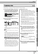
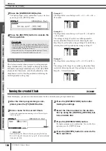
Страница 133: ...in number called up when the corresponding Step is selected 3 Program the Chain Setting the parameters for each Step Move the cursor to Step 01 then set the desired TYPE by using the data dial INC YES and DEC NO buttons When setting TYPE to KIT move the cursor and select the desired Drum Kit bank and number When setting TYPE to SONG select the desired Song number When setting TYPE to CLICK select ...

Страница 134: ...of the Steps 01 are called up when this Chain is selected Selecting the next Step calls up the settings of Steps 02 04 simultaneously Naming the created Chain F3 NAME From this display you can enter the desired name for the current chain up to eight characters 1 After the Chain programming is com pleted press the F3 NAME button 2 Enter a name for the current Chain For detailed instructions on nami...

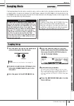
Страница 135: ...hen connecting low output equipment such as a micro phone electric guitar or bass set the Mic Line parameter to mic When connecting high output equipment such as a keyboard synthesizer or CD player set the Mic Line parame ter to line 6 Press the ENTER STORE button to store these settings IMPORTANT In order to use the Sampling function DIMM mod ules must be installed to the DTXTREME III When no DIM...

Страница 136: ...memory 4 Press the F2 SETTING button to call up the Sampling Setting display then make the necessary settings From this display you can set the basic parameters such as recording source and sampling frequency 1 Source Sampling Source Determines the input connector via which the signal to be sampled will be received AUX IN Analog audio from the AUX IN SAMPLING IN jacks is recognized as the recordin...

Страница 137: ...he Sampling Recording operation you can set the appropriate gain by checking the volume via the Level Meter while hitting the pad E F6 START Press this button to start Sampling When the Trigger mode 1 is set to level pressing the F6 START button calls up the WAITING indication on the display and actual Sampling does not start until the proper level signal is received When audio signal exceeding th...

Страница 138: ...K button to store the sampled sound as a User voice The F1 SELECT display appears again 13 If necessary repeat steps 5 12 to assign another User Voice to a different pad 14 Press the DRUM KIT button to enter the Drum Kit mode and then press the ENTER STORE button to store the Drum Kit settings For instructions see page 42 This makes it possible to store the User Voice Assignment as a Drum Kit If y...

Страница 139: ...ine in the waveform display When the cursor is not located on the Loop parameter the Loop Point is indicated as a vertical dotted line in the waveform display C End End Point Determines the End point for playback of the audio data included in the User Voice The portion of the audio to the right of this point will not be played back When the cursor is located on the End parameter the End Point is i...

Страница 140: ...ing the End Point area Pressing the F5 DISPLAY in this condition alter nates between the split screen display and a display showing either the Start Point area Loop Point area or the End Point area depending on which parameter has been selected 4 Specify the playback only portion of the audio data in the User Voice by using the data dial INC YES and DEC NO but tons In this step you can set the Sta...

Страница 141: ...nt matches the settings of the Beat time signature and Measure B Beat Time signature Determines the time signature of User Voice playback Setting the value here changes the End Point so that the length between the Start Point and the End Point matches the set tings of the Tempo and Measure C Meas Measure and beat Determines the length measure and beat of User Voice play back Setting the value here...

Страница 142: ...ress the F6 OK button if you are satis fied with the result of the Job operation If you are not satisfied with the result of the Job operation press the F5 CANCEL button and go back to Step 4 9 Save the created User Voice data to a USB storage device For detailed instructions on saving see pages 55 and 114 Basic Procedure of the Sampling Jobs NOTE When the User Voice contains no audio data pressin...

Страница 143: ...he length of the User Voice also changes the playback tempo of the audio data included in the User Voice 1 Ratio Determines the length of the post process Voice as a ratio of the length of the original Voice 100 The tempo change and the appropriate Ratio value can be calculated as follows Ratio value original tempo modified tempo x 100 B Accuracy Determines the quality of the resulting Voice by sp...

Страница 144: ... Determines which channel or both channels of the stereo User Voice will be converted to a mono User Voice L R mono The left and right channels of a stereo Sam ple are mixed and converted to a mono Sam ple L mono The left channel of a stereo Sample is con verted to a mono Sample R mono The right channel of the stereo sample is con verted to a mono sample 07 Loop Remix This Job lets you automatical...

Страница 145: ...gn each of the slices to a different User Voice Set the Select parameter to the desired slice number set the Save To parameter to the User Voice num ber as assignment destination then press the ENTER STORE button to execute the Assignment operation The advantage of this feature is that you can assign each rhythmic slice to be triggered by a different pad or note number and thus the rhythm can be r...

Страница 146: ... delete all User Voices 13 Extract This Job lets you delete from memory all unnecessary audio data included in the User Voice located ahead of the Start Point and located after the End Point leaving only the portion of the sample you wish to keep 1 User Voice bank and number Determines the User Voice bank and number of which the unnecessary portion is to be extracted 14 Optimize Memory This Job op...

Страница 147: ...nt to other devices Leaving the power cord connected while working can result in electric shock Leaving other cables connected can interfere with work Be careful not to drop any screws inside the instrument during installa tion This can be prevented by keeping the optional units and cover away from the instrument while attaching If this does happen be sure to remove the screw s from inside the uni...

Страница 148: ...using a Phillips screwdriver 4 Insert the two DIMMs into the DIMM sock ets Location for DIMM installation Installing the DIMM modules to the sockets 4 1 Press the ejector levers to the outside of the socket 4 2 Insert the DIMM vertically in the socket Press the DIMM in firmly until it snaps or locks in place Confirm whether or not both the levers are firmly locked DIMM Installation IMPORTANT Keep ...

Страница 149: ...AMPLING button then press the SF6 INF button page 136 If the DIMMs have been installed properly the appro priate available memory size is indicated in the display 1 Press the ejector lever until the DIMM unlocks 2 Pull the DIMM vertically out of the socket NOTE When you re install the cover make sure to steady the cover from the side with your hand NOTE If the DIMMs have not been installed properl...

Страница 150: ...uced depending on the settings of these parameters Check the Effect and Filter settings No sound may be produced especially depending on the Filter settings The external MIDI tone generator produces no sound Is the MIDI cable connector properly connected page 20 Make sure the MIDI Transmit Channels of the DTXTREME III match the MIDI Receive Channels of the connected external MIDI tone generators F...

Страница 151: ... the dis play called up via UTILITY F5 MIDI SF3 OTHER If you are connecting a computer to the DTX TREME III via USB this parameter should be set to USB if you are connecting a MIDI device to the DTX TREME III via MIDI this parameter should be set to MIDI Cannot save data to the external USB storage device Has the USB storage device you re using been properly formatted page 123 Is the USB storage d...

Страница 152: ...ound may continue when the Receive Key Off parameter is set to off in the display called up via DRUM KIT F2 VOICE SF4 OTHER The Pad Controller does not work as expected Check the Pad Controller Type parameter page 92 in the display called up via DRUM KIT F5 PAD SF1 PAD CTRL If this parameter is set to off the Pad Controller installed to the connected pad does not work Select the appropriate value ...

Страница 153: ...r cannot be loaded in the current mode Illegal file name The specified file name is invalid Try entering a different name Illegal input An invalid input or value has been specified Check the input method or value Illegal sample data The sample file specified for loading is unusable by the DTXTREME III Illegal selection An unacceptable file has been specified in the Song job mode Illegal song numbe...

Страница 154: ...annot be exe cuted Seq data is not empty This message appears if you attempt to record to a track that already contains data Clear the track data in the Song Job mode or select a different track then perform the Record operation Seq memory full The internal memory for Sequence data is full preventing any further operation such as recording Job execution or loading from the USB storage device Try a...

Страница 155: ... 8 User 1 Training Functions Measure break Groove check Rhythm gate Sampling Samples 1 016 for the User Voices Sampling Sources Audio input signals via AUX IN SAMPLING IN Audio output signals via OUTPUT Resample Sample Data Bits 16bit Sampling Frequency 44 1kHz 22 05 kHz 11 025 kHz 5 5125 kHz stereo mono Sampling Memory Optionally installed expandable to 512 MB 256 MB DIMM x 2 slots DIMMs are not ...

Страница 156: ...sure 102 Demo Songs 35 Destination Drum Kit number 97 Destination measure number 101 Destination Track number 101 DeviceNo 131 DIGITAL OUT connector 12 DIMM 76 147 DISPLAY 140 DISTORTION 70 Double triggering 108 DRAM 76 DRUM 39 Drum Kit 30 36 40 62 Drum Kit Bank 125 DRUM KIT button 10 Drum Kit icon 30 Drum Kit No 125 Drum Kit number 30 Drum Trigger 7 Drum Voice 40 62 Dry Level 81 E Edge Shot 28 29...

Страница 157: ...0 NUMBER Chain number 132 Number of measures to be inserted 102 O Open Rim Shot 28 Open Close 28 Optimize Memory 146 OTHER 39 OUTPUT L MONO and R jacks 12 OutputSel 128 OutputSel Output Select 81 107 Overdub 43 P Pad 16 Pad Assign 138 Pad Controller 59 92 Pad Controller Type 92 Pad Function 126 Pad Song 35 93 Pad Type 109 PadFunc 126 PAGE 80 82 84 90 91 94 128 129 PAN 96 103 Pan 81 128 Pan Depth 1...

Страница 158: ...Input jack as copy source 111 Trigger Input Level Indicator 26 Trigger Input Source 58 61 Trigger Level 137 Trigger No 125 Trigger Setup 26 60 Trigger Setup List 27 Trigger Setup number 26 Trigger Setup number as copy destination 111 Trigger Setup number as copy source 111 Trigger Signals 58 TriggerNo 26 TrigLink Trigger Link 94 TrigMono Poly Trigger Mono Poly 94 TrigVelocity Trigger Velocity 94 T...

Страница 159: ...ha Scandinavia AB J A Wettergrens Gata 1 Box 30053 S 400 43 Göteborg Sweden Tel 031 89 34 00 DENMARK YS Copenhagen Liaison Office Generatorvej 6A DK 2730 Herlev Denmark Tel 44 92 49 00 FINLAND F Musiikki Oy Kluuvikatu 6 P O Box 260 SF 00101 Helsinki Finland Tel 09 618511 NORWAY Norsk filial av Yamaha Scandinavia AB Grini Næringspark 1 N 1345 Østerås Norway Tel 67 16 77 70 ICELAND Skifan HF Skeifan...

Страница 160: ...oduct drums Yamaha Manual Library http www yamaha co jp manual U R G Pro Audio Digital Musical Instrument Division Yamaha Corporation 2007 Yamaha Corporation WM47120 001PODH 01B0 Printed in Japan EN OWNER S MANUAL This document is printed on chlorine free ECF paper with soy ink ...

Отзывы: