13
Optional Extras
• Connection via Ethernet
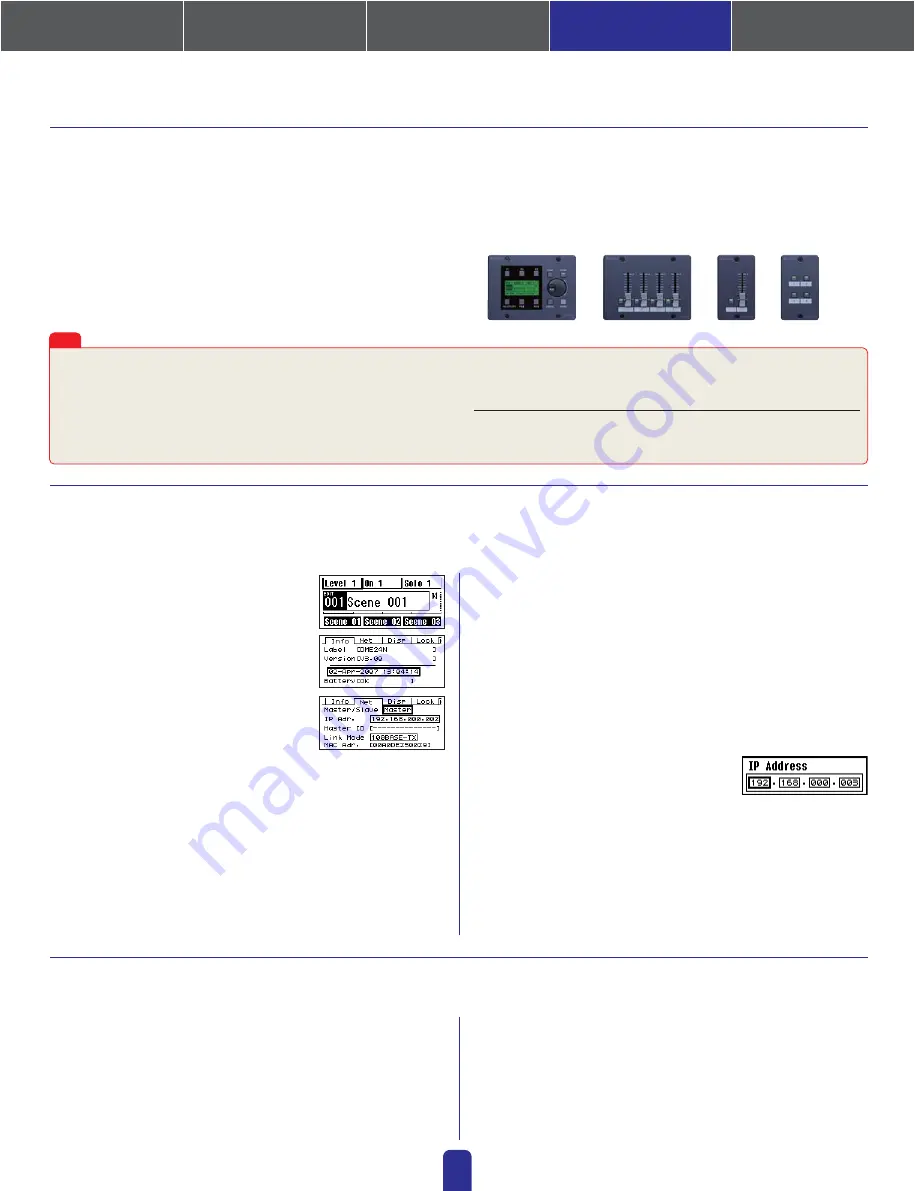
Intelligent Control Panel ICP1
• Connection via General Purpose Interface (GPI)
Control Panel CP4SF, Control Panel CP1SF, or Control Panel CP4SW
1.
Turn on the DME64N/24N.
2.
Press the [HOME] key to display the
main screen.
3.
Press and hold the [UTILITY] key for at
least 2 seconds to display the Utility
screen.
4.
Press the [UTILITY] key several times
until the Net page appears.
5.
Use the [
▲
] and [
▼
] keys to move the
cursor to the parameters listed below and press the [ENTER] key.
The corresponding editing dialog will appear. Set each of the following
parameters as described and press the [ENTER] key each time to confirm
and enter the settings.
•
Master/Slave
This parameter sets device-group master or slave status.
Master: One DME unit must be assigned as the master in each device group.
Slave: All other DME units in the group should be set to slave.
Note:
When DME64N/24N and DME Satellite units are combined in a device group,
be sure to assign a DME Satellite unit as the group master.
ICP1, CP4SF, CP1SF, and CP4SW controllers are available as optional extras for remote external control of the DME units. For details regarding
installation of a control panel and connection to the DME unit, please refer to the owner’s manual that came with the control panel.
Device group and IP address settings for DME64N and DME24N units can be made directly via their front panels as follows.
●
The latest information about DME units and applications can be
downloaded from the Yamaha Pro Audio website.
http://www.yamahaproaudio.com
●
The latest version of the DME unit firmware can be downloaded from
the Yamaha ProAudio website.
http://www.yamahaproaudio.com/downloads/firm_soft/index.html
Setting up DME64N/24N Networks via Panel Operations
Related web site on DME Units and peripherals
4. In-depth Information on DME Units
•
IP Address
This parameter sets the IP address of the DME unit in question. All DME
units in the same device group must share the same network address.
Notes:
1. When only one DME unit (Master) is used, the IP address should be set to
“192.168.0.2”.
2. The subnet mask is fixed at “255.255.255.0”.
3. The host address can be set between 2 and 253 for the master device, and
between 3 and 253 for slaves.
4. Unless it is absolutely necessary to use a global IP address, you should
always use a private address (that is, 192.168.0.2. through
192.168.255.253). Consult with your network administrator if a global
address must be used.
•
Master ID
When a device is assigned as a slave using
Master/Slave above, this parameter sets
the host address for the corresponding
master. Setting of this parameter is not
possible when the DME unit in question
is assigned as the master.
•
Link Mode
Ensure that “100Base-TX” is selected for this parameter.
6.
Press the [HOME] key to return and save your changes.
Whenever making GPI settings, check for responses using the GPI Setup page.
The GPI Setup page from the DME unit's Utility Display can be used to
monitor in real time the signals being input via the GPI IN terminal. This
can prove extremely useful in identifying the cause of GPI control prob-
lems after configuration as being within the GPI device, within the connec-
tions, or within the DME configuration. If the DME unit fails to operate as
required even though a signal is returned to the GPI IN terminal, the prob-
lem probably lies in the configuration data, or although unlikely, in the
DME unit itself. As this page can be used to check for GPI responses
when making GPI settings, it can be employed to great effect.
Maximum length of GPI cables
CPEV cables with a core diameter of 0.65 mm or more can be used over
distances of up to 100 m.
Tips
●
Library data for DMEseries Speaker Processor Components is available
from the”Downloads” page of the Yamaha Pro Audio website:
http://www.yamahaproaudio.com/downloads/documents/index.html
●
For information on touch panel controllers, visit:
AMX's web site:
http://www.amx.com/
CRESTRON's web site:
http://www.crestron.com/
Connecting to External Devices
2
3
4
1. Installing the Software
4. In-depth information
on DME Units
3. Advanced Setup
(via Ethernet cables)
2. Basic Setup
(via USB cable)
Appendix: Detailed
DME-N Network Driver Settings
ICP1
CP4SF
CP1SF
CP4SW


