


Getting Star
ted
2
DM1000 Editor—Owner’s Manual
Getting Started
Overview of DM1000 Editor
DM1000 Editor enables you to remotely control the Yamaha DM1000 mixing console and to save
the parameter settings on your computer. To use DM1000 Editor, you must first perform the fol-
lowing operations:
1
Start and configure Studio Manager.
2
Start and configure DM1000 Editor.
3
Synchronize DM1000 Editor with your DM1000 console (see page 4).
For more information on using Studio Manager, refer to the Studio Manager Owner’s Manual.
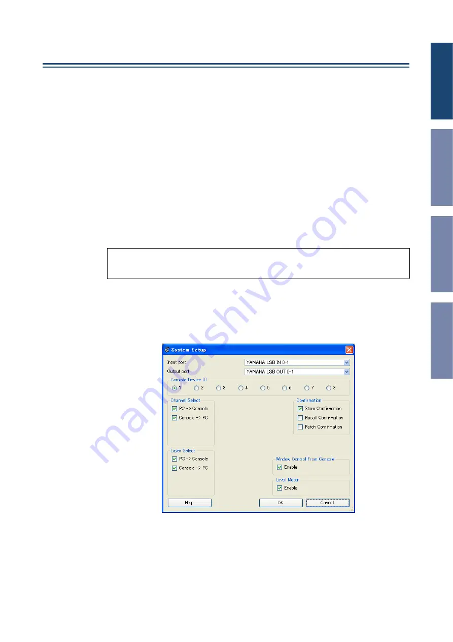
Configuring DM1000 Editor
You must configure the following settings for each open Editor.
❏
System Setup
To open the System Setup window, choose [System Setup] from the [File] menu.
Be sure to specify the Input port and Output port.
Input port/Output port:
From the ports you specified in Studio Manager, select the ports that
the editor will use to communicate with the DM1000 console.
Console Device ID:
DM1000 Editor can control any one of up to eight DM1000 consoles, each
with its own exclusive ID. Select the ID of the console you want to control.
Note:
• Specify MIDI ports in the Setup window of Studio Manager before making the following settings.
• To open each Editor, double-click the icon of the console or device you want to edit.