background image


7


DM1000 Editor—Owner’s Manual


Getting Star

ted


Ke

yboar

d Shor

tcuts


Inde

x


 Windo

ws


Using DM1000 Editor Windows
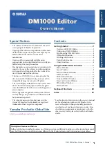
 

Master Window


The Master window enables you to switch between layers and control Stereo Out sig-
nals. To open this window, choose [Master] from the [Windows] menu.


A


[ONLINE]/[OFFLINE] button


Repeatedly clicking this button toggles between online and offline status.


This indicator is displayed when DM1000 Editor is connected to the 
DM1000 correctly. If the connection is correct, the DM1000 Editor 
parameters will work in unison with the DM1000 parameters.

This indicator is displayed when DM1000 Editor is not connected or 
is not communicating with the DM1000, or when you have selected 
Offline Edit. If the connection is incomplete, the DM1000 Editor 
parameters will not work in unison with the DM1000 parameters.
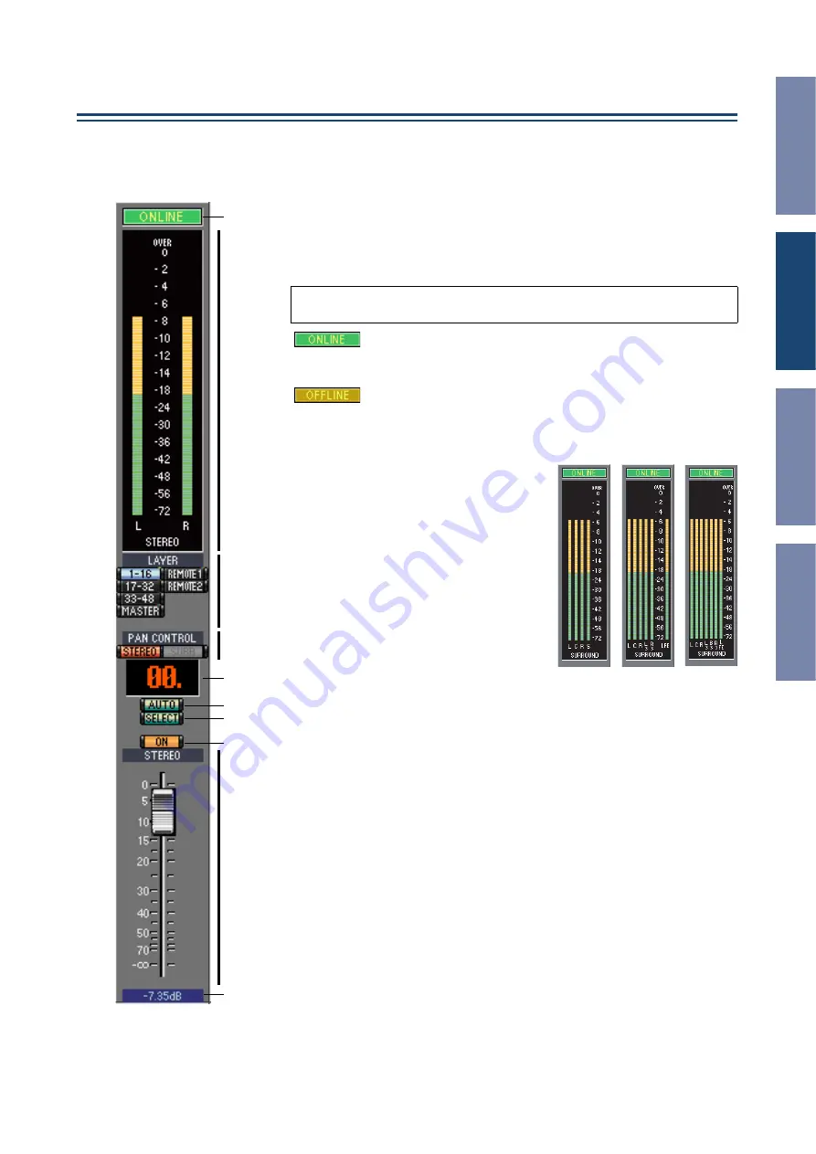
 

B


Meters


These meters display the output level of the 
Stereo Out when Surround mode is set to 
“STEREO,” or the Bus Outs used for sur-
round processing when Surround mode is 
set to 3-1, 5.1 or 6.1. The meters in 3-1, 5.1 
and 6.1 Surround modes are shown on the 
right.


C


LAYER buttons


These buttons are used to select the Layers.


D


PAN CONTROL


These buttons are used to select either 
“STEREO” (Stereo display mode) or 
“SURR” (Surround display mode). The 
Pan control on the Input Channels is a rotary control when “STEREO” is 
selected, and a dot on a pan graph when “SURR” is selected. If Surround mode is 
set to Stereo, the [SURR] button will be disabled.


E


Scene number display


This display indicates the currently-recalled scene’s number.


F


[AUTO] button


This button displays the Automix status of the Stereo Out.


G


[SELECT] button


This button is used to select the Stereo Out.


H


[ON] button


This button turns the Stereo Out on and off. It appears orange while the Stereo 
Out is on.


I


Master fader


This is the Stereo Out fader.


J


Fader value indicator


This indicator indicates the fader position in decibels (dB).


Note: 

If DM1000 Editor is not connected or is not communicating with the 

DM1000, clicking this button will not switch the unit from offline to online.

2

1

3

4

5

6
7

8

9

J

3-1

5.1

6.1

Содержание DM 1000

Страница 1: ...ll be announced separately The company names and product names in this Owner s Manual are the trademarks or registered trademarks of their respective companies Yamaha Pro Audio Global Site http www ya...

Страница 2: ...udio Manager Owner s Manual Configuring DM1000 Editor You must configure the following settings for each open Editor System Setup To open the System Setup window choose System Setup from the File menu...

Страница 3: ...nked When the PC Console option is on selecting a Layer in DM1000 Editor selects the same Layer on the con sole When the Console PC option is on selecting a Layer on the console selects the same Layer...

Страница 4: ...nization with the PC Console option to synchronize the console with DM1000 Editor The Offline Edit function is also activated when you click the ONLINE OFFLINE button in the Master window Working with...

Страница 5: ...function Please note however that after you perform one of the following operations you cannot success fully undo or redo any previous operation Operations on the console Closing Studio Manager Chang...

Страница 6: ...Ctrl click Move the cursor to a control or a parameter value then hold down the Ctrl key and click the mouse button to reset the value to the default e g to reset an Input Channel fader to or reset a...

Страница 7: ...ur round processing when Surround mode is set to 3 1 5 1 or 6 1 The meters in 3 1 5 1 and 6 1 Surround modes are shown on the right C LAYER buttons These buttons are used to select the Layers D PAN CO...

Страница 8: ...ignal phase of the channel G INSERT button This button is used to turn on and off the Input Channel s Insert H GATE button This button is used to turn on and off the Input Channel s Gate I Gate open c...

Страница 9: ...RR the control appears as dot on a pan graph The surround pan position can be set by dragging the dot U LFE control When 5 1 or 6 1 Surround mode is selected this control is used to set the surround L...

Страница 10: ...g G DELAY button This button is used to turn on and off the Bus Out s Delay function H Delay parameter This parameter is used to set the delay time of the Delay function Delay times can be set by drag...

Страница 11: ...r This is the Bus Out s fader F Fader value indicator This indicator indicates the fader position in the range of 0 through 127 If the remote target is set to User Assignable Layer In this case the as...

Страница 12: ...er and choose from the list that appears The LIBRARY button opens the Channel Library window B GATE section This section contains the Gate controls and display graph for the currently selected Input C...

Страница 13: ...x Send controls for the currently selected Input Channel Use the rotary controls to set the Aux Send levels and click them to turn Aux Sends on and off Use the button below each Aux Send control to se...

Страница 14: ...et the Bus to Stereo send level and pan The AUTO button displays the Automix status The SOLO button is used to solo the Bus Out the ON button to turn the Bus Out on and off and the channel fader to se...

Страница 15: ...annel fader for the currently selectedAux Send The meter to the right of the fader indicates the signal level and the value indicator under the fader indicates the fader position in decibels dB E INSE...

Страница 16: ...alance control AUTO and ON and channel fader for the Stereo Out The meter to the right of the fader indicates the signal level and the value indicator under the fader indicates the fader position in d...

Страница 17: ...of the corresponding library in the console You can copy and sort the items in the list memories by dragging them between the panes Within the same pane you can copy a memory by dropping it on top of...

Страница 18: ...RE button This button is used to store the contents of the library to the specified location K RECALL button This button is used to recall the selected memory L FILE section This section displays the...

Страница 19: ...C AUTO SETUP button Clicking this button sets the patches on this page to their initial values D ALL CLEAR button This button clears all patches on this page E LIBRARY button This button opens the In...

Страница 20: ...page to their initial values D ALL CLEAR button This button clears all patches on this page E LIBRARY button This button opens the Output Patch Library window F Port names These are the Port names To...

Страница 21: ...nd type E Insert Out Patchbay This patchbay is used to patch output ports to the Insert Outs of Input Channels Bus Outs Aux Sends and the Stereo Out Active patches are indicated by a red dot To make a...

Страница 22: ...internal Effects processor 1 The parameters in this section are used to select inputs and outputs for Effects processor 1 B LIBRARY button This button opens the Input Patch Library window C Effects p...

Страница 23: ...e click it and type C LIBRARY button This button opens the Output Patch Library window D Port names These are the Port names To edit a name click it and type E Patchbay The patchbay is used to patch o...

Страница 24: ...ected Input Chan nel The surround pan can be set by dragging the dot Clicking a speaker icon will move the pan posi tion to the position of that icon C Surround pan position This is the current surrou...

Страница 25: ...sor select These buttons are used to select the internal effects processors B Effect select section The EFFECT NAME TYPE and IN OUT are the name type and I O configuration of the effect recalled to th...

Страница 26: ...AY REC section This is shown only if the selected effect type is FREEZE To start record ing sampling click the REC button and then click the PLAY but ton The progress bar shows the current recording l...

Страница 27: ...cate the amount of gain reduction being applied by the channel Gate COMP GR The meters indicate the amount of gain reduction being applied by the channel Compressor LEVEL The meters indicate the chann...

Страница 28: ...ses all windows Ctrl Alt W Option W Opens the Master window Ctrl 1 1 Opens the Layer window Ctrl 2 2 Opens the Selected Channel window Ctrl 3 3 Opens the Library window Ctrl 4 4 Opens the Patch Editor...

Страница 29: ...ch page 22 EFFECT TYPE 25 Effects 1 4 page 27 Effects processor 1 section 22 Effects processor select 25 Effects processors 2 4 section 22 EQ button 8 10 EQ curve 8 10 Equalizer Library 17 EQUALIZER s...

Страница 30: ...urrent Session with a new name 4 Scene number display 7 SELECT button 7 9 10 11 Selected Channel Window 12 Short channel name 9 10 Shortcuts keyboard 28 SOLO button 9 10 SOURCE parameter 8 STEREO butt...

Отзывы: