A
1
2
3
4
5
6
7
8
9
10
B
C
D
E
F
G
H
I
J
K
L
M
N
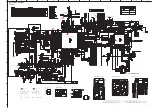
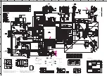
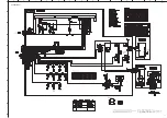
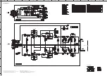
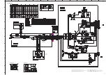
CD-S300
42
MAIN 2/2
★
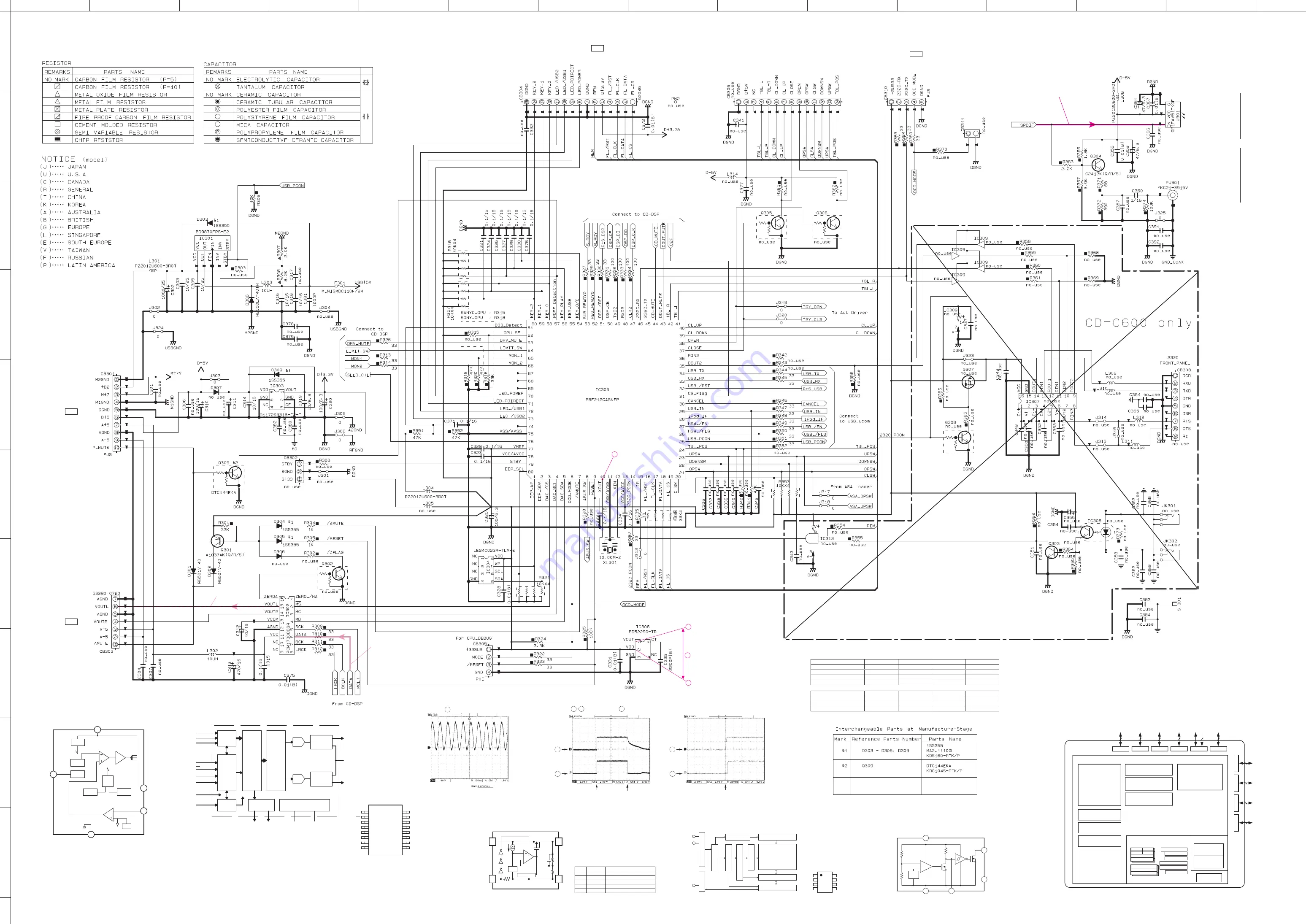
All voltages are measured with a 10MΩ/V DC electronic voltmeter.
★
Components having special characteristics are marked
⚠
and must be replaced
with parts having specifications equal to those originally installed.
★
Schematic diagram is subject to change without notice.
● 電圧は、内部抵抗 10MΩの電圧計で測定したものです。
● ⚠印のある部品は、安全性確保部品を示しています。部品の交換が必要な場合、
パーツリストに記載されている部品を使用してください。
● 本回路図は標準回路図です。改良のため予告なく変更することがございます。
IC313
JK301
JK302
IC308
IC307
CB308
IC309
IC309
IC309
IC309
IC309
CB302
CB301
CB303
CB305
CB311
CB310
CB306
CB304
ANALOG OUT L
ANALOG OUT
DIGITAL OUT
0
0
5.0
2.8
5.0
2.2
1.7
3.3
3.3
3.3
0
3.3
3.3
1.8
3.3
3.3
3.3
1.6
1.2
1.7
1.7
1.7
0
3.3
3.3
3.3
3.3
3.3
3.3
0
0
0
0
0
0
12.2
7.3
5.0
5.0
-5.0
-4.4
2.5
0
2.5
5.0
-5.0
-4.5
3.3
3.3
0
0
3.3
3.3
5.0
5.0
0
5.0
2.4
12.2
2.4
12.2
2.4
0.5
0
0
0
3.3
3.3
3.3
0
-4.5
3.3
3.3
3.3
3.3
-4.5
-4.5
-4.5
-4.5
5.0
5.0
0
0
5.0
2.5
2.5
2.5
3.3
3.3
3.3
3.3
3.3
3.3
3.3
0.2
3.3
3.3
3.3
3.3
3.3
3.3
3.3
3.3
3.3
3.1
0.2
3.3
3.2
3.3
3.3
3.3
0
0
3.2
3.2
0
0.6
1.7
1.5
0
3.3
3.1
2.8
0
0
3.3
0
3.3
0
3.3
3.3
3.3
3.3
3.3
3.3
3.3
3.3
1.7
0
0
0
0
0
0
0
0
0
0
0
0
3.3
0
0
0
0
0
3.2
3.3
0
3.3
3.3
3.3
0.9
0
3.3
3.3
3.3
0
3.3
3.3
3.3
3.3
3.3
3.3
3.3
3.3
3.1
2.8
0
0
3.3
3.3
0
0
POINT
C XL301 (Pin 10 of IC305)
1
IC306
(2 pin)
IC306
(1 pin)
2
1
IC306
(2 pin)
IC306
(1 pin)
2
POWER ON
POWER ON
POWER OFF
POINT
D 1 / IC306 (2 pin), 2 / CB306 (1 pin)
2
D
1
Vref
Vout
CT
GND
V
DD
NC
4
1
2
3
5
–
+
IC306
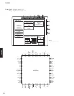
: BD5229G-TR
Voltage detector IC with adjustable output delay
OSC
PWM COMP
DRIVER
STBY
STBY
OUT
INV
GND
VCC
TSD
OCP
Error AMP
SS
CTL
LOGIC
IC301
: BD9870FPS-E2
High stand voltage 1 channel step-down switching regulator
VREF
1
5
FIN
4
2
Power Supply
Enhanced
Multilevel
Delta Sigma
Modulator
V
OUT
L
Oversampling
Digital
Filter
With
Function
Control
Audio
4/8
Serial
Port
BCK
LRCK
DATA
Serial
Control
Port
Zero Detect
(TEST)
SCK
System
Clock
Manager
MC (DEMP1)
MS (DEMP0)
Output Amp
and
Low Pass Filter
MD (MUTE)
DAC
V
COM
System Clock
AGND
V
CC
ZEROR/ZEROA
(1)
(ZEROA)
ZEROL/NA
(1)
Output Amp
and
Low Pass Filter
DAC
V
OUT
R
(FMT)
(1) Open-drain output for thePCM1782
NOTE: Signal names in parentheses ( ) are for the PCM1781.
ZEROR/ZEROA
V
OUT
L
V
OUT
R
V
COM
AGND
V
CC
NC
NC
16
15
14
13
12
11
10
9
ZEROL/NA
MS
MC
MD
SCK
DATA
BCK
LRCK
1
2
3
4
5
6
7
8
IC302
: PCM1780DBQR
Audio digital-to-analog converter
V
DD
CE
Pin No.
1
2, 5
3
4
6
Symbol
V
OUT
GND
CE
NC
V
DD
Description
Output Pin of Voltage Regulator
Ground Pin
Chip Enable Pin
No Connection
Input Pin
Vref
6
1
3
2,5
Current Limit
V
OUT
GND
IC303
: R1172S331B-E2-F
CMOS-based positive-voltage regulator IC
IC304
: LE24C023M-TLM-E
Two wire serial interface EEPROM
Write controller
WP
SCL
SDA
8
NC
NC
NC
GND
1
7
2
6
3
5
4
SDA
SCL
WP
VDD
I/O Buffer
Input Buffer
Condition detector
Serial controller
Address generator
X decoder
High voltage generator
Y decoder and Sense AMP
Serial-Parallel converter
EEPROM Array
IC305
: R5F212CASNFP
Single chip 16 bit microprocessor
R0H
Timers
Port P0
8
Port P6
8
Port P7
8
Port P8
8
Port P9
4
8
8
8
3
2
8
Port P1
Port P2
Port P3
Port P4
Port P5
System clock
generation circuit
XIN-XOUT
High-speed on-chip oscillator
Low-speed on-chip oscillator
XCIN-XCOUT
UART or
clock synchronous serial I/O
(8 bits x 3)
I
2
C bus or SSU
(8 bits x 1)
LIN module
Watchdog timer
(15 bits)
A/D converter
(10 bits x 20 channels)
D/A converter
(8 bits x 2)
Timer RA (8 bits x 1)
Timer RB (8 bits x 1)
Timer RC (16 bits x 1)
Timer RD (16 bits x 2)
Timer RE (8 bits x 1)
Timer RF (16 bits x 1)
R8C/Tiny Series microprocessor core
Memory
I/O ports
Peripheral functions
R0L
R1H
R1L
R2
SB
INTB
PC
USP
ISP
FLG
ROM
(1)
RAM
(2)
Multiplier
NOTES:
1. ROM size varies with MCU type.
2. RAM size varies with MCU type.
R3
A0
A1
FB
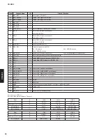
Key detection for A/D port
Key input (A/D) pull-up resistance 10 k-ohms
Ohm
0
+ 100
+ 3.3 k
+ 12.0 k
V
0
0.03 – 0.1
0.8 – 0.9
2.0 – 2.1
A/D value (3.3V=255)
0
3 – 7
60 – 70
150 – 160
KEY2 (60 pin)
–
PURE DIRECT
CD/USB
–
Ohm
0
+ 820
+ 3.3 k
+ 12.0 k
V
0
0.2 – 0.3
0.9 – 1.0
2.0 – 2.1
A/D value (3.3V=255)
0
15 – 25
70 – 78
153 – 162
KEY0 (58 pin)
–
STOP
PAUSE
OPEN/CLOSE
KEY1 (59 pin)
–
PLAY
SKIP +/ SKIP -/SEARCH -
EEPROM
DC/DC CONVERTER
LINER
REGULATOR
AUDIO DAC
DIGITAL
OUT
OPTICAL
COAXIAL
RESET IC
OUTPUT
(Writing port)
Содержание CD-S300
Страница 5: ...5 CD S300 CD S300 FRONT PANEL R T A G L J models R model T model REAR PANELS A model ...
Страница 6: ...6 CD S300 CD S300 L model G model J model ...
Страница 7: ...7 CD S300 CD S300 REMOTE CONTROL PANEL CDX8 ...
Страница 56: ...57 CD S300 CD S300 MEMO ...
Страница 57: ...CD S300 ...

