7-20
SIGNALING SYSTEM
SIGNALING SYSTEM
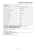
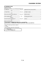
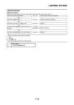
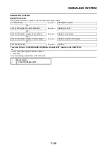
INSPECTION STEPS
If the speedometer will not operate, use the following inspection steps.
*1 marked: Refer to "CHECKING AND CHARGING THE BATTERY" section in the CHAPTER 3.
• Remove the following parts before inspection.
1. Headlight
• Use the following special tools in this inspection.
*1 Check battery.
No good
→
Recharge or replace.
OK
↓
Check each coupler and wire connection.
No good
→
Repair or replace.
OK
↓
Check multi-function display. (Input voltage)
No good
→
Replace wire harness.
OK
↓
Check multi-function display. (Output voltage)
No good
→
Replace multi-function display.
OK
↓
Check speed sensor.
No good
→
Replace.
Pocket tester:
YU-3112-C/90890-03112
Содержание 2010 WR450FZ
Страница 4: ......
Страница 12: ...1 2 LOCATION OF IMPORTANT LABELS EUROPE ...
Страница 13: ...1 3 LOCATION OF IMPORTANT LABELS AUS NZ ZA ...
Страница 49: ...2 18 TIGHTENING TORQUES ...
Страница 51: ...2 20 LUBRICATION DIAGRAMS 1 Intake camshaft 2 Exhaust camshaft A To main axle B From oil pump ...
Страница 90: ...3 31 ELECTRICAL Charging method using a variable voltage charger ...
Страница 91: ...3 32 ELECTRICAL Charging method using a constant voltage charger ...
Страница 108: ...5 5 CARBURETOR 13 Bracket cylinder head breather pipe 1 14 Carburetor joint 1 Order Part name Q ty Remarks ...
Страница 125: ...5 22 CYLINDER HEAD 3 Install Bolt cylinder head 1 Bolt cylinder head 10 Nm 1 0 m kg 7 2 ft lb ...
Страница 144: ...5 41 OIL PUMP 15 Oil pump drive shaft 1 16 Rotor housing 1 Order Part name Q ty Remarks ...
Страница 230: ...PRINTED IN JAPAN E PRINTED ON RECYCLED PAPER YAMAHA MOTOR CO LTD 2500 SHINGAI IWATA SHIZUOKA JAPAN ...

