6-11
FRONT BRAKE AND REAR BRAKE
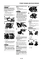
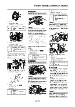
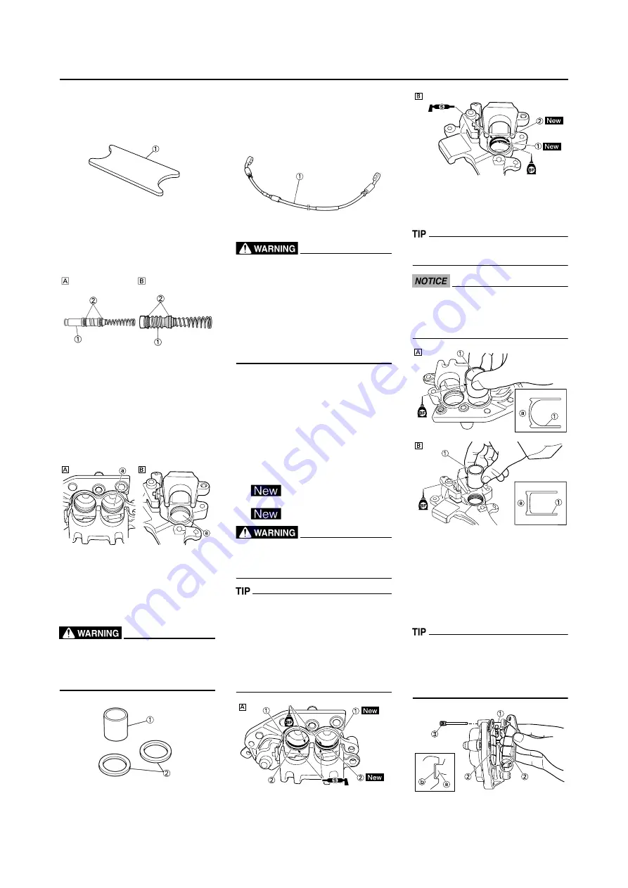
3. Inspect: (front brake only)
• Reservoir float "1"
Damage
→
Replace.
4. Inspect:
• Brake master cylinder piston "1"
• Brake master cylinder cup "2"
Wear/damage/score marks
→
Re-
place brake master cylinder kit.
A. Front
B. Rear
CHECKING THE BRAKE CALIPER
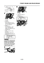
1. Inspect:
• Brake caliper cylinder inner sur-
face "a"
Wear/score marks
→
Replace
brake caliper assembly.
A. Front
B. Rear
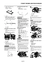
2. Inspect:
• Brake caliper piston "1"
Wear/score marks
→
Replace
brake caliper piston assembly.
Replace the brake caliper piston
seals and brake caliper piston dust
seals "2" whenever a caliper is dis-
assembled.
CHECKING THE BRAKE HOSE
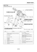
1. Inspect:
• Brake hose "1"
Crack/damage
→
Replace.
HANDLING NOTE
• All internal parts should be
cleaned in new brake fluid only.
• Internal parts should be lubricat-
ed with brake fluid when in-
stalled.
• Replace the brake caliper piston
seals and brake caliper piston
dust seals whenever a caliper is
disassembled.
INSTALLING THE BRAKE
CALIPER PISTON
1. Clean:
• Brake caliper
• Brake caliper piston seal
• Brake caliper piston dust seal
• Brake caliper piston
Clean them with brake fluid.
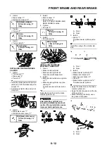
2. Install:
• Brake caliper piston seal "1"
• Brake caliper piston dust seal "2"
Always use new brake caliper pis-
ton seals and brake caliper piston
dust seals.
• Apply the brake fluid on the brake
caliper piston seal.
• Apply the silicone grease on the
brake caliper piston dust seal.
• Fit the brake caliper piston seals
and brake caliper piston dust seals
onto the slot on brake caliper cor-
rectly.
A. Front
B. Rear
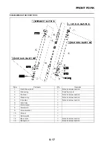
3. Install:
• Brake caliper piston "1"
Apply the brake fluid on the piston
wall.
• Install the piston with its shallow
depressed side "a" facing the
brake caliper.
• Never force to insert.
A. Front
B. Rear
INSTALLING THE FRONT BRAKE
CALIPER
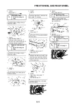
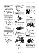
1. Install:
• Pad support "1"
• Brake pad "2"
• Pad pin "3"
• Install the brake pads with their pro-
jections "a" into the brake caliper re-
cesses "b".
• Temporarily tighten the pad pin at
this point.
Содержание 2010 WR450FZ
Страница 4: ......
Страница 12: ...1 2 LOCATION OF IMPORTANT LABELS EUROPE ...
Страница 13: ...1 3 LOCATION OF IMPORTANT LABELS AUS NZ ZA ...
Страница 49: ...2 18 TIGHTENING TORQUES ...
Страница 51: ...2 20 LUBRICATION DIAGRAMS 1 Intake camshaft 2 Exhaust camshaft A To main axle B From oil pump ...
Страница 90: ...3 31 ELECTRICAL Charging method using a variable voltage charger ...
Страница 91: ...3 32 ELECTRICAL Charging method using a constant voltage charger ...
Страница 108: ...5 5 CARBURETOR 13 Bracket cylinder head breather pipe 1 14 Carburetor joint 1 Order Part name Q ty Remarks ...
Страница 125: ...5 22 CYLINDER HEAD 3 Install Bolt cylinder head 1 Bolt cylinder head 10 Nm 1 0 m kg 7 2 ft lb ...
Страница 144: ...5 41 OIL PUMP 15 Oil pump drive shaft 1 16 Rotor housing 1 Order Part name Q ty Remarks ...
Страница 230: ...PRINTED IN JAPAN E PRINTED ON RECYCLED PAPER YAMAHA MOTOR CO LTD 2500 SHINGAI IWATA SHIZUOKA JAPAN ...

