1-7
CHECKING OF CONNECTION
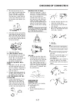
3. When disassembling the ma-
chine, keep mated parts together.
They include gears, cylinders,
pistons, and other mated parts
that have been "mated" through
normal wear. Mated parts must
be reused as an assembly or re-
placed.
4. During the machine disassembly,
clean all parts and place them in
trays in the order of disassembly.
This will speed up assembly time
and help assure that all parts are
correctly reinstalled.
5. Keep away from fire.
ALL REPLACEMENT PARTS
1. We recommend to use Yamaha
genuine parts for all replace-
ments. Use oil and/or grease rec-
ommended by Yamaha for
assembly and adjustment.
GASKETS, OIL SEALS AND O-
RINGS
1. All gaskets, oil seals, and O-rings
should be replaced when an en-
gine is overhauled. All gasket sur-
faces, oil seal lips, and O-rings
must be cleaned.
2. Properly oil all mating parts and
bearings during reassembly. Ap-
ply grease to the oil seal lips.
LOCK WASHERS/PLATES AND
COTTER PINS
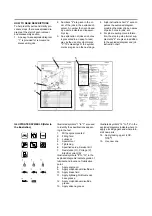
1. All lock washers/plates "1" and
cotter pins must be replaced
when they are removed. Lock
tab(s) should be bent along the
bolt or nut flat(s) after the bolt or
nut has been properly tightened.
BEARINGS AND OIL SEALS
1. Install the bearing(s) "1" and oil
seal(s) "2" with their manufactur-
er's marks or numbers facing out-
ward. (In other words, the
stamped letters must be on the
side exposed to view.) When in-
stalling oil seal(s), apply a light
coating of lightweight lithium base
grease to the seal lip(s). Oil the
bearings liberally when installing.
Do not use compressed air to spin
the bearings dry. This causes dam-
age to the bearing surfaces.
CIRCLIPS
1. All circlips should be inspected
carefully before reassembly. Al-
ways replace piston pin clips after
one use. Replace distorted cir-
clips. When installing a circlip "1",
make sure that the sharp-edged
corner "2" is positioned opposite
to the thrust "3" it receives. See
the sectional view.
CHECKING OF
CONNECTION
Dealing with stains, rust, moisture,
etc. on the connector.
1. Disconnect:
• Connector
2. Dry each terminal with an air
blower.
3. Connect and disconnect the con-
nector two or three times.
4. Pull the lead to check that it will
not come off.
5. If the terminal comes off, bend up
the pin "1" and reinsert the termi-
nal into the connector.
6. Connect:
• Connector
The two connectors "click" together.
7. Check for continuity with a tester.
• If there in no continuity, clean the
terminals.
• Be sure to perform the steps 1 to 7
listed above when checking the
wire harness.
• For a field remedy, use a contact re-
vitalizer available on the market.
• Use the tester on the connector as
shown.
Содержание 2010 WR450FZ
Страница 4: ......
Страница 12: ...1 2 LOCATION OF IMPORTANT LABELS EUROPE ...
Страница 13: ...1 3 LOCATION OF IMPORTANT LABELS AUS NZ ZA ...
Страница 49: ...2 18 TIGHTENING TORQUES ...
Страница 51: ...2 20 LUBRICATION DIAGRAMS 1 Intake camshaft 2 Exhaust camshaft A To main axle B From oil pump ...
Страница 90: ...3 31 ELECTRICAL Charging method using a variable voltage charger ...
Страница 91: ...3 32 ELECTRICAL Charging method using a constant voltage charger ...
Страница 108: ...5 5 CARBURETOR 13 Bracket cylinder head breather pipe 1 14 Carburetor joint 1 Order Part name Q ty Remarks ...
Страница 125: ...5 22 CYLINDER HEAD 3 Install Bolt cylinder head 1 Bolt cylinder head 10 Nm 1 0 m kg 7 2 ft lb ...
Страница 144: ...5 41 OIL PUMP 15 Oil pump drive shaft 1 16 Rotor housing 1 Order Part name Q ty Remarks ...
Страница 230: ...PRINTED IN JAPAN E PRINTED ON RECYCLED PAPER YAMAHA MOTOR CO LTD 2500 SHINGAI IWATA SHIZUOKA JAPAN ...

