5-24
VALVES AND VALVE SPRINGS
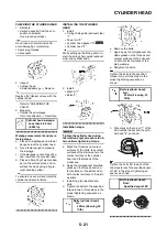
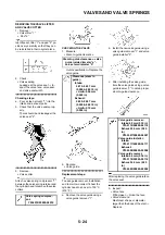
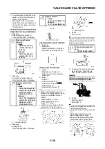
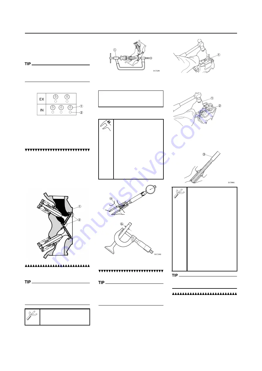
REMOVING THE VALVE LIFTER
AND VALVE COTTER
1. Remove:
• Valve lifter "1"
• Pad "2"
Identify each lifter "1" and pad "2" po-
sition very carefully so that they can
be reinstalled in their original place.
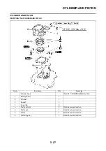
2. Check:
• Valve sealing
Leakage at the valve seat
→
In-
spect the valve face, valve seat
and valve seat width.
Checking steps:
a. Pour a clean solvent "1" into the
intake and exhaust ports.
b. Check that the valve seals prop-
erly.
There should be no leakage at the
valve seat "2".
3. Remove:
• Valve cotter
Attach a valve spring compressor "1"
between the valve spring retainer and
the cylinder head to remove the valve
cotters.
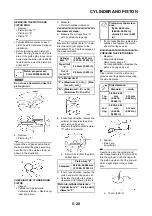
CHECKING THE VALVE
1. Measure:
• Stem-to-guide clearance
Out of specification
→
Replace the
valve guide.
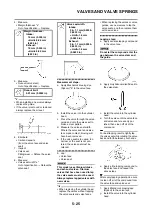
2. Replace:
• Valve guide
Replacement steps:
To ease guide removal, installation
and to maintain correct fit heat the
cylinder head in an over to 100 °C
(212 °F).
a. Remove the valve guide using a
valve guide remover "1".
b. Install the new valve guide using a
valve guide remover "1" and valve
guide installer "2".
c. After installing the valve guide,
bore the valve guide using a valve
guide reamer "3" to obtain proper
stem-to-guide clearance.
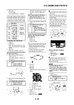
After replacing the valve guide reface
the valve seat.
3. Inspect:
• Valve face
Pitting/wear
→
Grind the face.
• Valve stem end
Mushroom shape or diameter
larger than the body of the stem
→
Replace.
Valve spring compres-
sor:
YM-4019/90890-04019
Stem-to-guide clearance = valve
guide inside diameter "a" -
valve stem diameter "b"
Clearance (stem to
guide):
Intake:
0.010–0.037 mm
(0.0004–0.0015 in)
<Limit>:0.08 mm
(0.003 in)
Exhaust:
0.020–0.047 mm
(0.0008–0.0019 in)
<Limit>:0.10 mm
(0.004 in)
Valve guide remover:
Intake:4.5 mm (0.18 in)
YM-4116/90890-04116
Exhaust:5.0 mm (0.20
in)
YM-4097/90890-04097
Valve guide installer:
Intake:
YM-4117/90890-04117
Exhaust:
YM-4098/90890-04098
Valve guide reamer:
Intake:4.5 mm (0.18 in)
YM-4118/90890-04118
Exhaust:5.0 mm (0.20
in)
YM-4099/90890-04099
Содержание 2010 WR450FZ
Страница 4: ......
Страница 12: ...1 2 LOCATION OF IMPORTANT LABELS EUROPE ...
Страница 13: ...1 3 LOCATION OF IMPORTANT LABELS AUS NZ ZA ...
Страница 49: ...2 18 TIGHTENING TORQUES ...
Страница 51: ...2 20 LUBRICATION DIAGRAMS 1 Intake camshaft 2 Exhaust camshaft A To main axle B From oil pump ...
Страница 90: ...3 31 ELECTRICAL Charging method using a variable voltage charger ...
Страница 91: ...3 32 ELECTRICAL Charging method using a constant voltage charger ...
Страница 108: ...5 5 CARBURETOR 13 Bracket cylinder head breather pipe 1 14 Carburetor joint 1 Order Part name Q ty Remarks ...
Страница 125: ...5 22 CYLINDER HEAD 3 Install Bolt cylinder head 1 Bolt cylinder head 10 Nm 1 0 m kg 7 2 ft lb ...
Страница 144: ...5 41 OIL PUMP 15 Oil pump drive shaft 1 16 Rotor housing 1 Order Part name Q ty Remarks ...
Страница 230: ...PRINTED IN JAPAN E PRINTED ON RECYCLED PAPER YAMAHA MOTOR CO LTD 2500 SHINGAI IWATA SHIZUOKA JAPAN ...

