6-18
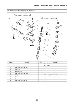
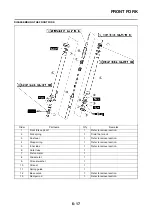
FRONT FORK
HANDLING NOTE
Support the machine securely so
there is no danger of it falling over.
The front fork requires careful atten-
tion. So it is recommended that the
front fork be maintained at the deal-
ers.
To prevent an accidental explosion
of air, the following instructions
should be observed:
• The front fork with a built-in pis-
ton rod has a very sophisticated
internal construction and is par-
ticularly sensitive to foreign ma-
terial. Use enough care not to
allow any foreign material to
come in when the oil is replaced
or when the front fork is disas-
sembled and reassembled.
• Before removing the cap bolts or
front forks, be sure to extract the
air from the air chamber com-
pletely.
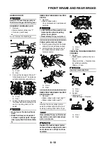
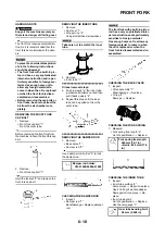
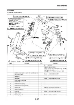
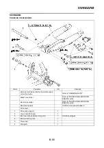
REMOVING THE FRONT FORK
CAP BOLT
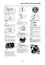
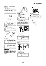
1. Remove:
• Front fork cap bolt "1"
From the outer tube.
Before removing the front fork from
the machine, loosen the front fork cap
bolt.
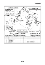
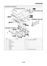
2. Remove:
• Front fork cap bolt "1"
Hold the locknut "2" and remove the
front fork cap bolt.
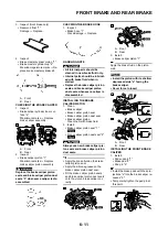
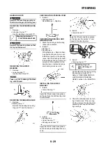
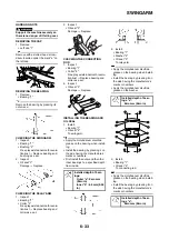
REMOVING THE INNER TUBE
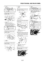
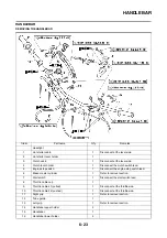
1. Remove:
• Dust seal "1"
• Stopper ring "2"
Using slotted-head screwdriver.
Take care not to scratch the inner
tube.
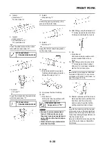
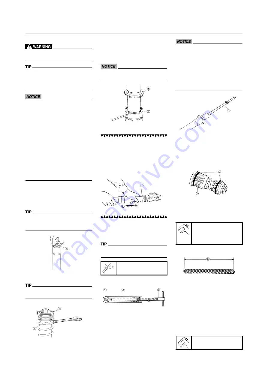
2. Remove:
• Inner tube "1"
Oil seal removal steps:
a. Push in slowly "a" the inner tube
just before it bottoms out and then
pull it back quickly "b".
b. Repeat this step until the inner
tube can be pulled out from the
outer tube.
REMOVING THE DAMPER ROD
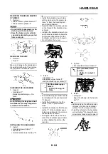
1. Remove:
• Base valve "1"
• Damper rod "2"
Use a damper rod holder "3" to lock
the damper rod.
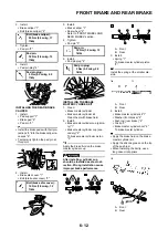
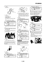
CHECKING THE DAMPER ROD
1. Inspect:
• Damper rod "1"
Bend/damage
→
Replace damper
rod.
The front fork with a built-in piston
rod has a very sophisticated inter-
nal construction and is particularly
sensitive to foreign material.
Use enough care not to allow any
foreign material to come in when
the oil is replaced or when the
front fork is disassembled and re-
assembled.
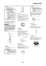
CHECKING THE BASE VALVE
1. Inspect:
• Valve assembly "1"
Wear/damage
→
Replace.
• O-ring "2"
Damage
→
Replace.
CHECKING THE FORK SPRING
1. Measure:
• Fork spring free length "a"
Out of specification
→
Replace.
CHECKING THE INNER TUBE
1. Inspect:
• Inner tube surface "a"
Score marks
→
Repair or replace.
Use #1,000 grit wet sandpaper.
Damaged oil lock piece
→
Re-
place.
• Inner tube bends
Out of specification
→
Replace.
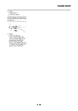
Use the dial gauge "1".
Damper rod holder:
YM-01494/90890-01494
Fork spring free length:
460 mm (18.1 in)
<Limit>: 455 mm (17.9
in)
Inner tube bending limit:
0.2 mm (0.008 in)
Содержание 2010 WR450FZ
Страница 4: ......
Страница 12: ...1 2 LOCATION OF IMPORTANT LABELS EUROPE ...
Страница 13: ...1 3 LOCATION OF IMPORTANT LABELS AUS NZ ZA ...
Страница 49: ...2 18 TIGHTENING TORQUES ...
Страница 51: ...2 20 LUBRICATION DIAGRAMS 1 Intake camshaft 2 Exhaust camshaft A To main axle B From oil pump ...
Страница 90: ...3 31 ELECTRICAL Charging method using a variable voltage charger ...
Страница 91: ...3 32 ELECTRICAL Charging method using a constant voltage charger ...
Страница 108: ...5 5 CARBURETOR 13 Bracket cylinder head breather pipe 1 14 Carburetor joint 1 Order Part name Q ty Remarks ...
Страница 125: ...5 22 CYLINDER HEAD 3 Install Bolt cylinder head 1 Bolt cylinder head 10 Nm 1 0 m kg 7 2 ft lb ...
Страница 144: ...5 41 OIL PUMP 15 Oil pump drive shaft 1 16 Rotor housing 1 Order Part name Q ty Remarks ...
Страница 230: ...PRINTED IN JAPAN E PRINTED ON RECYCLED PAPER YAMAHA MOTOR CO LTD 2500 SHINGAI IWATA SHIZUOKA JAPAN ...

