61U5H11
7-26
9
8
7
6
5
4
3
2
1
Clamp bracket and swivel bracket
6.
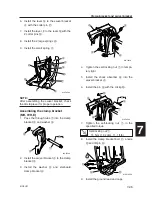
Install the lever
y
to the swivel bracket
4
with the cotter pin
u
.
7.
Install the lever
i
to the lever
y
with the
2 cotter pins
o
.
8.
Install the 2 large springs
p
.
9.
Install the small spring
a
.
NOTE:
After assembling the swivel bracket, check
the tilt stop lever for proper operation.
Assembling the clamp bracket
(MH, WH, E)
1.
Pass the through tube
1
into the clamp
bracket
2
and washer
3
.
2.
Install the swivel bracket
4
to the clamp
bracket
2
.
3.
Install the washer
5
and starboard
clamp bracket
6
.
y
i
a
p
4
p
u
o
o
61U70560
4.
Tighten the self-locking nut
7
in tempo-
rary tight.
5.
Install the shock absorber
8
into the
swivel bracket
4
.
6.
Install the pin
9
with the circlip
0
.
7.
Tighten the self-locking nut
7
in the
specified torque.
8.
Install the clamp bracket bolt
q
, anode
w
and tilt pin
e
.
9.
Install the ground lead and caps.
Self-locking nut
7
:
15 N·m (1.5 kgf·m, 11.1 ft·lb)
61U70500
1
3
2
61U70510
5
4
6
2
61U70520
9
7
8
4
0
e
w
q
61U070530
61U5H11_07_1 06.2.13 1:24 PM Page 29
Содержание 115B
Страница 1: ...115B SERVICE MANUAL 61U 28197 5H 11 140B E115A E115A 115B 140B ...
Страница 4: ......
Страница 79: ...61U5H11 4 18 9 8 7 6 5 4 3 2 1 MEMO ...
Страница 136: ...POWR 5 55 61U5H11 Power unit MEMO ...
Страница 159: ...61U5H11 6 22 9 8 7 6 5 4 3 2 1 Shimming Shimming 6G46090E T3 M3 M4 M1 M2 T1 T2 F R P ...
Страница 255: ......
Страница 256: ...YAMAHA MOTOR CO LTD Printed in Japan Oct 2005 1 2 1 E_1 Printed on recycled paper E115A 115B 140B ...


