Electric Chain Hoist CPE/F
6
6. Loosely replace the second side plate (item 6) on the crossbars (item
1). The washers (item 3), hex. nuts (item 2) and locknuts (item 9) can
be fitted loosely.
7. Raise the complete pre-assembled trolley to the carrying beam.
8. Engage the second side plate (item 6) ensuring that the roll pins (item
8) engage into one of the bores in the round nuts (item 5). To achieve
this it may be necessary to rotate the round nuts slightly.
9. Tighten the hex nuts (item 2) on the second side plate. Tighten the
locknuts (item 9) finger-tight and then a further ¼ to ½ turn.
Attention:
The locknuts must always be fitted!
10. By traversing the trolley check the following:
• that a clearance of 2 mm is maintained on each side between the
trolley wheel flanges and the beam outer edge.
• that the suspension traverse and consequently the unit is centred
below the beam.
• that all 4 locknuts (item 9) are fitted.
• that the side plates are parallel.
• that all wheels roll freely and make good contact with the flange of
the beam.
• that there are no obstacles on the driving surface.
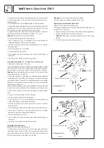
Assembly of the trolley 7,5 - 10 t (vgl. Fig. 11 und Fig. 12)
1. Measure the flange width of the beam.
2. Evenly distribute the spacer sleeves and spacer washers on both
sides of the load bar. The clearance between the trolley wheel flange and
the beam edge must be 2 mm on both sides when finally assembled.
Attention:
When installing the load bar look out for the spacer for the
supporting frame (Fig. 11 and 12).
3. Place the side plates on the load bar and distribute the remaining
spacer washers on the outside of the side plates equally on both sides
ensuring that at least 1 large and 3 small adjusting washers are mounted
between the side plate and hexagon slotted nut. Secure one side plate
with a hexagon slotted nut.
Tip:
For easier mounting screw one side plate tightly. The other side plate
is attached loosely. Pay attention to the desired position of the drive side.
4. Then lift the entire unit to the beam and tighten all hexagon slotted
nuts.
5. Secure all hexagon slotted nuts with cotter pins.
6. By traversing the trolley check the following:
• that a clearance of 2 mm is maintained on each side between the
trolley wheel flanges and the beam outer edge.
• that the suspension traverse and consequently the unit is centred
below the beam.
• that both hexagon slotted nuts are fitted and secured with cotter pins.
• that at least 1 large and 3 small adjusting washers are mounted
between the side plate and hexagon slotted nut
• that the side plates are parallel.
• that all wheels roll freely and make good contact with the flange of
the beam.
• that there are no obstacles on the driving surface.
Assembly of the hand chain
(Model VTG with hand chain drive only)
To fi t the hand chain position the slot on the outer edge of the hand
chain wheel below the chain guide. Place any one link of the endless
hand chain vertically into the slot and turn the hand chain wheel until
the link has passed the chain guides on both sides.
Attention:
Do not twist the hand chain when fi tting!
Geared trolleys are moved by pulling the hand chain.
Shortening or extending the hand chain
(Model CPE/F with hand chain drive only)
The length of the hand chain should be adjusted so that the distance to
the floor is 500 - 1000 mm.
1. Determine the open link of the hand chain and open up by bending.
2. Shorten or extend the hand chain as required.
Attention:
The number of removed or added chain links must always
be even.
3. Close the open connecting link by bending.
Trolley
Travel motor
Control box
Travel motor
Control box
Trolley
Distance washer
Crossbar
Crossbar
Distance washer for joke
Distance washer for joke
Joke
Joke
Trolley adaption 7,5 t
Trolley adaption 10 t
Fig. 12
Fig. 11
Distance washer
Содержание CPEF
Страница 15: ...Electric Chain Hoist CPE F 15...
Страница 16: ...Electric Chain Hoist CPE F 16...
Страница 17: ...Electric Chain Hoist CPE F 17...


