Electric Chain Hoist CPE/F
11
chain must be fi tted so that the welds on the standing links face towards
the chain guide in the housing. Operate the hoist in the lowering direction
(
-button) to feed the chain through the hoist.
4. Replace chain end stop
Slide the buff er pad over the loose end of the load chain and refi t the
chain end stop ensuring that at least 1 link remains free (see Fig. 1).
5. Fitting the chain anchor bolt
Inspect the chain anchor bolt for fl aws, cracks or burrs. Enter the last link
of the other load chain end into the slot in theunderside of the hoist body.
Attention:
The chain must not be twisted.
Now enter the chain anchor bolt through the side bore. Move the last
link back and forth while entering the chain anchor bolt to ensure that
it is not trapped and damaged by the anchor bolt. Secure the anchor
bolt with the grub screw.
6. Assemble the bottom block
Check the idler sheave for damage. Position the load chain over the
idler sheave ensuring that the welds on the standing links face away.
Grease the needle bearings in the bottom block halves. Place the load
hook assy in the slot provided in one of the bottom block halves and
push the complete unit onto the idler sheave. Ensuring that the buff er
pad is situated correctly in its groove replace the second bottom block
half and secure with the screws.
7. Functional test
All units with two or more chain strands must be inspected before every
operation for twisted or kinked chains. Chains on 2-strand units may
become twisted if the bottom block is rolled over. If a strand is twisted
disconnect it from the hoist and re-thread it correctly. In some cases it
may be necessary to remove the last link.
8. Before initial operation lubricate the unloaded chain and test all hoist
functions under a no-load condition.
8.4 MAINTENANCE LOAD HOOK
Inspect the hooks for deformation, damage, surface cracks, wear and
signs of corrosion as required but at least annually. Adverse working
conditions may dictate shorter periods. Hooks that do not fulfi l all require-
ments must be replaced immediately. Welding on hooks to compensate
for wear or damage is not permissible.
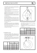
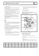
Hooks must be replaced when the mouth of the hook has opened
more than 10 % (Fig. 15) or the nominal value of other dimensions has
decreased by 5 % due to wear. Nominal dimensions and wear limits are
shown in the following table.
Fig. 16
CPE/F 16 / 20
CPE/F 32 / 40 / 50
CPE/F 25 / 30
CPE/F 75 / 100
Inspection
Dim.
nominal
min.
nominal
min.
value
value
value
value
[mm]
[mm]
[mm]
[mm]
Hook
saddle
b
2
24
22,8
29,5
28
Hook
saddle
h
2
35
33,2
44,5
42,3
Hook
opening
a
2
43
47,3 54
59,4
Hook
opening
a
1
37
40,7 46 50,6
The axial clearance
Δ
of the load hook in the direction of force in the
bottom block and in the cross head assy. (see Fig. 17) has to be deter-
mined additionally at every inspection.
If the measurement is larger than 1 mm a special maintenance service
is required for the hook head, the balls and the bottom block resp. the
cross head assy.
The following lower limits are to be obtained:
CPE/F 16 / 20
CPE/F 32 / 40 / 50
CPE/F 25 / 30
CPE/F 75 / 100
Inspection
Dim.
min. Dim. in mm
min. Dim. in mm
Diameter of ball
4,75
5,7
Hook head
α
6,3
7,9
Bottom block
β
8
9,2
Axial clearance
Δ
1 1
Fig. 17
Содержание CPEF
Страница 15: ...Electric Chain Hoist CPE F 15...
Страница 16: ...Electric Chain Hoist CPE F 16...
Страница 17: ...Electric Chain Hoist CPE F 17...


