Electric Chain Hoist CPE/F
10
8.3 LOAD CHAIN
The load chains are case-hardened and carry the designations
11 x 31 DAT.
The CPE/F electric hoists are specially designed to use this type of chain.
For this reason only chains that have been approved by the manufacturer
may be used in these hoists.
Lubricating the load chain
The load chain is to be lubricated before initial operation and every month,
however, latest after 50 operating hours. Adverse working conditions,
e. g. excessive dust or continued heavy duty can dictate shorter periods
between lubrication.
• Before the chain is lubricated it must be cleaned. Flame cleaning
is forbidden. Use only cleansing methods and agents that do not
corrode the chain material. Avoid cleansing methods that can lead to
hydrogen brittleness, e g. spraying or dipping chain in caustic solvents.
Also avoid surface treatments that can hide cracks and flaws or other
surface damage.
• The chain must be lubricated in a no-load condition so that lubricant
can enter between the links, e. g. by dipping in oil. The chain i s to be
lubricated throughout itsentire length.
• Motor oil of the voscosity 100, e. g. Shell Tonna T68 can be used to
lubricate the chain. For very dusty applications use a dry lubricant.
Inspecting the load chain for wear
Load chains must be inspected every 3 months or the latest after 200
operating hours.
Visually inspect the chain over its full length for deformation, cracks,
fl aws, elongation, wear or corrosive pitting.
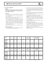
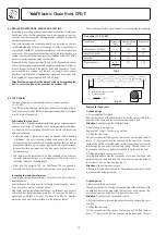
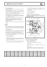
Link chains must be replaced when the nominal thickness d on any part
of the chain has been reduced by more than 10 % or when the pitch t is
elongated by more than 5 % or over 11 pitches (11 x t) by 2 %. Nominal
dimensions and wear limits are shown in the following table 2.
2-strand design
1. Remove the chain anchor bolt
The chain anchor bolt is situated on the underside of the hoist body. With
an allen key remove the grub screw that serves as locking device. Tap
out the chain anchor bolt with a drift from the other side.
Attention:
Do not damage anchor bolt or bore.
2. Pull the load chain through the bottom block and remove the chain
end stop.
3. Fitting the new chain
Cut the second to last link open on the loose end of the load chain to
form a "C". Remove the last link and connect the new chain. The new
Replace the load chain
1-strand design
1. Disassemble bottom block
Remove the circlip with suitable pliers. Raise the swivel tube in the
direction of the chain and tap out the chain bolt with a drift.
Attention:
Do not damage the chain bolt bore.
2. Remove the chain end stop.
Remove the 2 screws. The chain is now free.
3. Fitting the new chain
Cut the second to last link open on the loose end of the load chain to
form a "C". Remove the last link and connect the new chain. The new
chain must be fi tted so that the welds on the standing links face towards
the chain guide and away from the load sheave. Operate the hoist in
the lowering direction (
-button) to feed the chain through the hoist.
4. Fitting lower block and chain end stop
Slide the end buff ers over the loose ends of the load chain and refi t
bottom block and chain end stop. The chain end stop must be fi tted so
that at least 1 link remains free (see Fig. 1).
Attention:
Use new hexagon locknuts.
5. Before initial operation lubricate the unloaded chain and test all hoist
functions under no-load condition.
t
11 x t
Fig. 15
d
1
d
2
8.2 REGULAR INSPECTIONS, SERVICE AND TESTING
According to prevailing national/international occupational safety and
health regulations, hoisting equipment must be inspected at least an-
nually by a competent person. Adverse working conditions may dictate
shorter inspection periods.
The commissioning and inspection details can be noted on the test
certifi cate delivered with the hoist or on page 14 of this manual. Repairs
may only be carried out by specialist workshops that use original Yale
spare parts. The inspection must determine that all safety devices are
present and fully operational and cover the condition of the hoist, lifting
gear, accessories and supporting constructions.
If required by the Occupational Health and Safety Organisation, the re-
sults of the adequate inspections and competent performance of repairs
have to be substantiated. If the electric hoist (with capacity of 1 t and
up) is installed in a carriage, or if the load is moved in one or several
directions, the installation is considered as crane and inspections have
to be carried out in accordance with BGV D6-Cranes.
Attention! Power supply must be disconnected while inspecting the
device, unless the type of the examination excludes this.
Chains that do not fulfi l all requirements must be replaced immediately.
Tab. 2
Link chains 11 x 31 DAT
Inspection
Dimension Nominal value
Wear limit
[mm]
[mm]
Length over 11 pitches
11 x t
341
347
Length of 1 pitch
t
31
32
Diameter
d
11,3
Mean thickness
d
1
+ d
2
11,3 10,2
2
d = Nominal thickness of chain
d
1
, d
2
= Actual value
d
1
+ d
2
d
m
=
≤ 0,9 d
2
Содержание CPEF
Страница 15: ...Electric Chain Hoist CPE F 15...
Страница 16: ...Electric Chain Hoist CPE F 16...
Страница 17: ...Electric Chain Hoist CPE F 17...


