4
Installation
18
07.2020
ba
-o
.2
.6
.0
-us
-3
.2
-ys
|
A1
18
67
50
1 Re
v A
E
4
Installation
WARNING
Improper assembly can cause material damage or severe injuries.
➢
Ensure that the supporting structure is designed for the maximum hoist load.
➢
Ensure that a competent person carries out the assembly.
➢
Adhere to the national and local safety and accident prevention regulations, the
occupational safety acts and environmental provisions.
➢
Work that cannot be carried out from floor level must always be carried out from lifting
platforms.
➢
Use a safety harness when performing any work outside of lifting platforms.
➢
Wear the prescribed personal protective equipment.
➢
Secure the danger zone.
➢
Maintain a sufficient safety distance from the product.
➢
Use only original mounting accessories from the manufacturer.
➢
Tighten the bolted connections to the specified tightening torques.
➢
Secure the trolleys during assembly, e.g. with straps, so that they cannot fall.
4.1
Stationary hoist
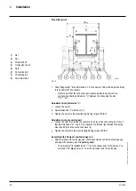
Fig. 6
Type
M
T
(rope drum torque)
[lb
f
in]
YKA/SKA
M
T
= 0.5 × F × 5 in
YKB/SKB
M
T
= 0.5 × F × 6.6 in
YKC/SKC
M
T
= 0.5 × F × 8.6 in
YKE/SKE
M
T
= 0.5 × F × 14 in
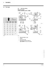
Possible mounting positions and fleet angles
Feet “at bottom” and “at top” are possible for designs with bottom hook block (rope lead
-
off vertically downwards).
The YK/SK wire rope hoist with 1PS and 1PS twin hook rope lead-off can be installed in
various positions (fleet angles see section
4.2 Fleet angle
)
1.
If possible, install the hoist in the
preferred installation position
***
(see section
4.2.1 Attachment at bottom
)
2.
Use the fixing elements specified, see the following figures and tables.
3.
Take care that no distortion arises from unevenness (see figure item
A = max. 0.5°
,
item
B = max. 0.079 in
).
4.
The customer's substructure must take up the torque M
T
from the rope drum. It must
therefore be torsion resistant.
5.
If the rope lead-off is not vertical, the shearing forces arising must be taken up by a
shear bar.
6.
For tightening torques see chapter
Tightening torques.
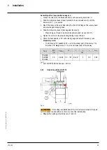
Standard reevings
1PS
2PS
4PS
1PD
2PD
4PD
Fig. 7

