7
Inspection and maintenance
07.2020
99
ba
-o
.2
.6
.0
-us
-3
.2
-ys
|
A1
18
67
50
1 Re
v A
E
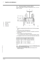
Disassemble electrical connection of the brake.
Unscrew the fastening screws (4)
Remove coil carrier (5) complete with anchor plate (6).
Take off brake rotor (7).
NOTICE
When dampening the cloths,
only use
isopropyl alcohol. The use of brake
cleaner is
not
permissible
.
–
Ensure sufficient drying time for the cleaned surfaces.
We cannot recommend cleaning the rotor / friction linings because oil / grease has usually
worked into the lining and this can only be removed from the surface area to a limited
degree. Furthermore, it is not possible to fully exclude negative reactions between the
cleaning products and the lining. We therefore recommend use of the spare parts kit here.
Check friction surfaces for wear and clean with a damp cloth.
Slide a new brake rotor (7) onto the hub (8) and check the available clearance.
NOTICE
Danger of damage
–
If increased clearance is present in the gearing between the brake rotor (7) and
hub (8), remove the hub (8) from the motor shaft and replace it. Be sure to consult
the production factory before removing the hub (8).
Clean coil carrier.
Replace the brake pressure springs (see section
Replacing the pressure springs
).
Check the O-ring of the coil carrier for damage and replace if necessary.
Assemble in reverse order.
–
Steps 6 to 11 are omitted.
–
Make sure that the inspection bore for the air gap measurement is in the lower
area.
–
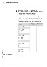
After tightening the fastening screws (4) (for tightening torque see Tab. 28), mark
the fastening screws (4).
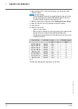
Hoist motor type
Hoist brake
S max.
a
Tightening torque (4)
[in]
[in]
[lb
f
ft]
12/2H33-MF10Z-106
NM38722
0.024
1
7
12/2H42-MF10X-106
NM38732
0.024
1
7
12/2H62-MF11X-106
NM38742
0.031
1
16
12/2H71-MF11X-106
NM38742
0.031
1
16
12/2H72-MF13Z-106
NM38754
0.035
1.2
16
12/2H91-MF16ZC-106
NM38790
0.035
1.6
33
Tab. 28
Check the brake data against the rating plate on the hoist motor!

