120
FT-857 Operating Manual
O
PTIONAL
F
ILTERS
: YF-122S, YF-122C,
AND
YF-122CN
1. Turn the transceiver’s power off by pressing and holding in the PWR switch for one
second, then disconnect the DC cable from the
INPUT
jack on the rear panel of the
transceiver.
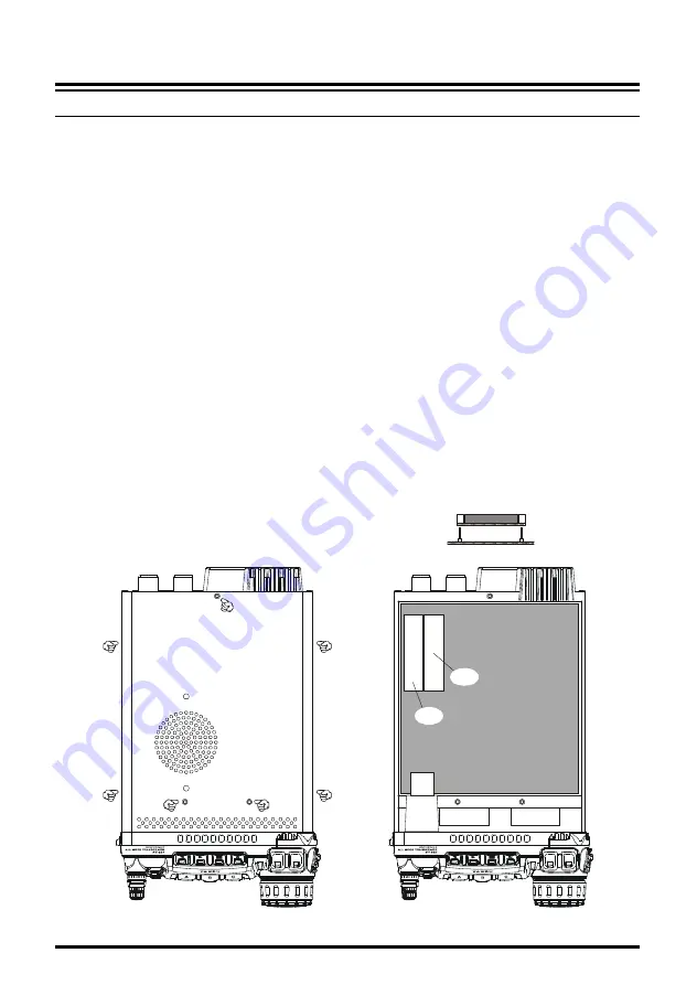
2. Referring to Figure 1, remove the seven screws affixing the top cover of the transceiver
then disconnect the speaker’s connector from the MAIN Unit.
3. Refer to Figure 2 for the mounting locations for the optional filters. Position the filter so
that its connectors are aligned with the mounting pins on the board, and push it into place
(these slots does not distinction for the installed filter).
4. Replace the top cover and its seven screws (remember to replace the internal speaker’s
plug).
5. Filter installation is now complete. Connect the DC cable to the
INPUT
jack.
To use the optional filter, press the [
B
](
2.3
,
500
, or
300
) (in Multi Function Row “n”) to
activate the optional filter which is installed in the “
FIL1
” slot. Press the [
C
](
2.3
,
500
, or
300
) key (in Multi Function Row “n”) to activate the optional filter which is installed in the
“
FIL2
” slot.
Note
: If you wish to use the optional filter for transmission while operating in the SSB mode,
change the setting of Menu Mode
No-086
[
TX IF FIL-
TER
]
to “
FIL1
” or “
FIL2
” (the slot into which you in-
stalled the optional
YF-122S
filter).
I
NSTALLATION
OF
O
PTIONAL
A
CCESSORIES
BAND
DWN
UP
TX/BUSY
DSP
MODE
Figure 1
Figure 2
ê
MAIN UNIT
Optional Filter
BAND
DWN
UP
TX/BUSY
DSP
MODE
FIL-2
FIL-1


