34
Manual
US 3.10 713 FLOW CONVERTER 1905 - SW 833062
MJK Automation
Blokken 9
DK-3460 Birkerød
Denmark
Tel
+45 45 56 06 56
www.mjk.com
Actual level (0.5 ft)
Bottom of sensor
e.g.
4
ft.
Appendix E
System Package 2 - Shuttle
®
used as
signal amplifier
To ensure a correct flow measurement when using
a Shuttle
®
as signal amplifier, the mA signal from the
Shuttle
®
must correspond to the selected level range on
the MJK 713. Four parameters must therefore be set on
the Shuttle
®
: the measuring unit, the zero point, the level
range and the mA output zero/span.
The keyboard is used for the initial programming of the
Shuttle
®
and is therefore hidden behind the front lid. The
keys are marked with symbols indicating their function.
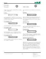
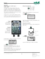
Display
LCD-display with
symbols for indication
during programming
and normal service.
Keyboard
Keyboard with a
brief instruction for
programming the
SONOLEV™.
The lower part can be
tipped up to show the
terminal designations.
When Shuttle
®
is connected to the power supply for the
first time, the following display will appear:
Press
(ENTER) once.
At the same moment Shuttle
®
registers an echo, the
zero point is automatically adjusted to the level that is
present in the flume or weir.
Furthermore, the mA output is set to 4 mA at the current
zero point and 20 mA at a level corresponding to a dis-
tance of 14 in from the ultrasonic sensor.
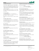
Setting of measuring unit
The measuring unit should be set to the same unit as
used on the MJK 713.
Press
(UNIT) once.
Select the measuring unit with the UP/DOWN keys and
confirm with ENTER.
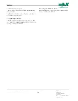
Setting of level readout
The level readout should be set to the actual level in the
flume / weir.
Press
again.
Use the UP/DOWN keys and confirm with ENTER.

