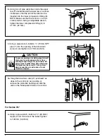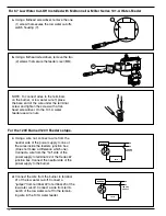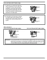
k.
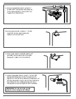
Using two (2) pipe wrenches, rotate the upper
tee (P) clockwise and the lower tee (J) counter-
clockwise so that the end of the tube can be
inserted into the lower compression fitting (K).
NOTE: Make sure that the control is in a hori-
zontal position. Using an adjustable wrench,
tighten the lower compression fitting (K) to
31 ft•lb (42 N•m).
K
J
P
6
T
U
V
l.
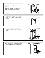
Using a pipe wrench, install a
w
" (19mm) NPT
pipe (T) into the opening of the blow down
valve (U) and tighten to 47 ft•lb (64 N•m).
A
W
m.
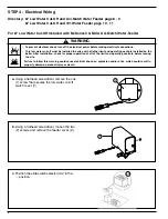
Hang the blow down card (W) (enclosed) as
close to the control (A) as possible, or
remove the protective backing and affix the
card on the boiler jacket close to the control.
X
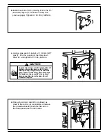
a.
Using a pipe wrench, install a 2
2
" (63.5mm)
nipple (X) into the side of the boiler. Tighten
to 109 ft•lb (148 N•m).
For Series 767
To prevent burning or scalding, pipe blow-off
discharge from blow-down valve to floor –
allowing enough height for a pail under dis-
charge pipe to collect blow down discharge.
This pipe must be same 3/4” size as blow-
down connection; do not reduce. Do not
thread end of pipe.
!
CAUTION
Содержание McDonnell & Miller 67 Series
Страница 1: ...INSTRUCTION MANUAL MM 201H Series 67 and 767 Low Water Cut Offs For Steam Boilers...
Страница 9: ......

