background image

Xylem Inc.


8200 N. Austin Avenue 

Morton Grove, Illinois 60053 

Phone: (847) 966-3700 

Fax: (847) 965-8379

www.mcdonnellmiller

.com

McDonnell & Miller is a trademark of Xylem Inc. or one of its subsidiaries. 

MAINTENANCE

SCHEDULE:

• Blow down weekly (at least once) when the 

boiler is in operation.

• Disassemble and inspect annually. Replace 

the low water cut-off if it is worn, corroded,

or if components no longer operate properly.

• Inspect the float chamber and equalizing 

piping annually. Remove all sediment 

and debris.

• Replace every 10 years.

More frequent replace-

ment may be required when severe conditions 
exist such as rapid switch cycling, surging water 
levels, and use of water treatment chemicals.

PROCEDURE:

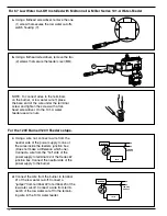
1. Blow down the low water cut-off when the 

water level is at its normal level and the 
burner is on. Fully open the blow down 
valve and observe the water level fall in the
gauge glass. Close the valve after verifying 
that the feeder contacts have closed and 
the burner shuts off. If this does not happen, 
immediately shut off the boiler and correct 
the problem.

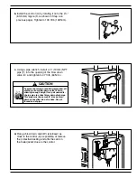
To prevent serious personal injury from steam and hot
water, make sure there is a discharge line from the
blow down valve to a proper place of disposal.

Failure to follow this caution could cause
personal injury.

!

CAUTION

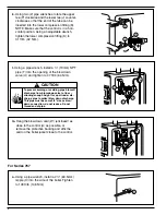
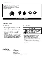
INSTALLATION COMPLETE

For All Installations

BOTTOM

TOP

LEFT

RIGHT

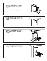
The BX outlet (GG) on the control is movable
into any of the four positions by simply
removing the two black-headed screws and
rotating the housing.

© 2014 Xylem Inc.  MM-201H  March 2014   Part No. 246752

Содержание McDonnell & Miller 67 Series

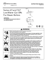
Страница 1: ...INSTRUCTION MANUAL MM 201H Series 67 and 767 Low Water Cut Offs For Steam Boilers...

Страница 2: ...C For Series 67 The elevation of the control A is already determined by the location of the gauge glass tappings B C on the boiler The horizontal cast line D should be located at or above the boiler m...

Страница 3: ...ntrol and tighten a 2 13mm NPT pipe plug G provided into the tapping on the bottom of the control body A Tighten the pipe plug to 31 ft lb 42 N m A F G When using the tape sealant on the external thre...

Страница 4: ...install the pipe tee P provided onto the nipple M in the upper tapping N Tighten to 31 ft lb 42 N m N M P f Using an adjustable wrench install 1 2 13mm NPT compression fitting base U into the upper te...

Страница 5: ...sing a pencil mark the tubing Q for proper insertion into the compression fitting K Remove the tubing Q and using the tube cutter cut the tubing to its proper length Q K 5 i Using two 2 pipe wrenches...

Страница 6: ...down valve U and tighten to 47 ft lb 64 N m A W m Hang the blow down card W enclosed as close to the control A as possible or remove the protective backing and affix the card on the boiler jacket clo...

Страница 7: ...lb 148 N m d Hang a blow down card W enclosed as close to the control A as possible or remove the protective backing and affix the card on the boiler jacket close to the control To prevent burning or...

Страница 8: ...peration of all of the limit and operating controls before leaving the site Failure to follow this warning could cause electrical shock an explosion and or a fire which could result in property damage...

Страница 9: ......

Страница 10: ...der For the 120V Burner 120V Feeder setups BURNER 120 VAC SUPPLY 1 2 3 4 N H 101A 69 c Using a wire nut connect a wire from the neutral side of the power supply to one of the wires inside the feeders...

Страница 11: ...nal 1 of the low water cut off Connect a wire from terminal 4 of the low water cut off to the remaining wire in the water feeder Wire nut together BURNER 101A 120 VAC SUPPLY N H 24V 1 2 3 4 69 Wiring...

Страница 12: ...ment chemicals PROCEDURE 1 Blow down the low water cut off when the water level is at its normal level and the burner is on Fully open the blow down valve and observe the water level fall in the gauge...

Отзывы: