background image

CH-180                    CH-210                      CH-240 
CH-240 ASME 

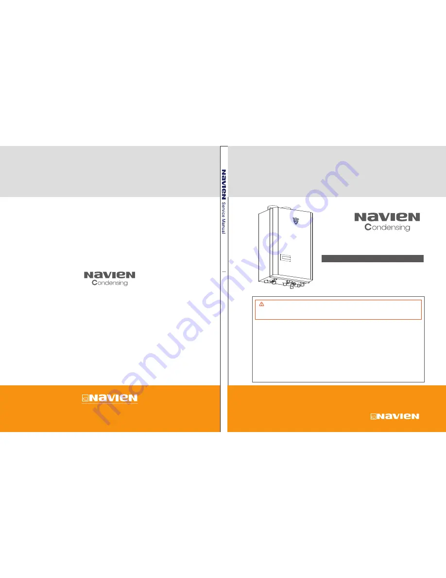
Combination Water Heater

/ Heating Boiler

MODEL

CH


Combination Water Heater / Heating Boiler

Combination Water Heater / Heating Boiler

Ver. 1.00

Service Manual Service Manual

Service Manual

Navien America, Inc.

20 Goodyear lrvine, CA 92618

TEL +949-420-0420   FAX +949-420-0430

www.naviennamerica.com

1

st

 Edition - July 2010

No. 20A-GT-002

Do not store or use gasoline or other flammable vapors and liquids in the vicinity

      of this or any other appliance.

WHAT TO DO IF YOU SMELL GAS


Installation and service must be performed by a qualified installer,

  service agency or the gas supplier. 

WARNING 

If the information in this manual is not followed exactly, a fire or explosion may result causing

property damage, personal injury or loss of life.

● 

Do not try to light any appliance.

● 

Do not touch any electrical switch; do not use any phone in your building.

● 

Immediately call your gas supplier from a neighbor’s phone. Follow the gas supplier’s

    instructions.

● 

If you cannot reach your gas supplier, call the fire department. 

Summary of Contents for CH-180

Page 1: ...nd liquids in the vicinity of this or any other appliance WHAT TO DO IF YOU SMELL GAS Installation and service must be performed by a qualified installer service agency or the gas supplier WARNING If...

Page 2: ......

Page 3: ...16 2 1 PRODUCT INFORMATION 16 2 2 LAYOUT AND KEY COMPONENTS 17 3 TECHNICAL DATA 18 3 1 GENERAL SPECIFICATIONS 18 3 2 DIMENSIONS 19 4 SYSTEM DETAILS 20 4 1 SCHEMATIC AND WATER FLOW DIAGRAM 20 4 1 1 Spa...

Page 4: ...8 4 6 17 DHW Heat Exchanger 49 4 6 18 Circulation Pump 50 4 6 19 3 Way Valve 51 4 6 20 Water pressure Sensor 52 4 6 21 Auto Feeder Valve 53 5 TROUBLESHOOTING 54 5 1 ERROR CODE LIST 54 5 2 01ERROR 56 5...

Page 5: ...113 6 2 2 Adjusting the Gas Air Ratio 114 7 MAINTENANCE 116 7 1 DRAINING THE BOILER 116 7 2 CLEANING THE INTAKE AIR FILTER 117 7 3 FLUSHING THE HEAT EXCHANGER 117 8 REPLACEMENT OF PARTS 118 8 1 REPLAC...

Page 6: ...Feeder Valve 136 8 2 18 Domestic Hot Water Exchanger 137 8 2 19 Domestic Hot Water Outlet Collar 138 9 COMPONENTS DIAGRAM AND PART LIST 139 9 1 CASE DISASSEMBLE 139 9 2 BURNER DISASSEMBLE 141 9 3 WATE...

Page 7: ...Navien America Inc 2010 CH series service Manual 5 Version 1 0 Revisions Version Description of changes Date 1 00 First Issue July 30 10...

Page 8: ...nt part s will be warranted only for the remaining portion of the original component part s Applicable Warranty Period EFFECTIVE DATE The Effective Date of warranty coverage the beginning of the Appli...

Page 9: ...ng Damages malfunctions or the all failures caused by conversion from natural gas to LP gas or LP gas to natural gas or attempt to operate with a type of gas not specified for the combination water he...

Page 10: ...al Navien America Inc reserves all rights related to this manual This manual should be accessible only to technical service personal authorized by Navien America Inc Read and understand the safety inf...

Page 11: ...PCB EMI HTL General name of CH 180 CH 210 and CH 240 and CH 240 ASME Natural Gas Liquid Gas Air Pressure Air Pressure Sensor Domestic Hot Water Fan Motor Gas Air Ratio Control Gallon per Minute Gas Pr...

Page 12: ...personal injury hazards Observe all of the safety messages that follow this symbol to avoid possible injury of death Indicates an imminently hazardous situation which if not avoided could result in s...

Page 13: ...ace anything in or around the vent terminals that could obstruct the air flow in and out of the boiler such as a clothes line DANGER FLAMMABLE VAPORS Vapors from flammable liquids will explode and cat...

Page 14: ...he boiler if any of the vent pipes vent elbows and or the boiler i damaged in any way ii have separated at a joint iii are cracked or show evidence of corrosion rusting or melting HOT WATER TEMPERATUR...

Page 15: ...and will settle on the floor Do not smoke Extinguish any open flames and sparks Do not operate light switches or electrical equipment switches Do not use any phone in your building Open the windows an...

Page 16: ...adjustment alteration service or maintenance can cause property damage personal injury or death To prevent scalding always check the temperature of the hot water after servic ing DO NOT attempt to ch...

Page 17: ...oltage may cause abnormal operation and may reduce the life expec tancy of this prod uct Navien units come from the factory configured for use with either Liquid Propane LP or Natural Gas NG Before st...

Page 18: ...maximum outputs The appliance always dives priority to DHW supply The appliance is designed to be used with a circulation pump a divert valve assembly a flow sensor a DHW plate heat exchanger and safe...

Page 19: ...Auto Feeder Valve Main Gas Valve Description DHW Flow Sensor Syphon Transformer Gas Pressure Sensor Gas Pipe Secondary Heat Exchanger Primary Heat Exchanger APS Venturi Burner Ignition Transformer Ai...

Page 20: ...ut off Device Ignition Operation Detector Water Temperature High Limit Switch Exhaust Temperature High Limit Switch Plumb Easy Valve Set Outdoor Sensor Pressure Relief Valve Condensate Neutralizer Com...

Page 21: ...nual 19 Version 1 0 3 2 Dimensions A Connection Diameter Description Exhaust Air lntake A B C D E F G H 3 3 1 1 3 4 3 4 3 4 1 2 Heating Supply Connection Heating Return Connection Hot Water Outlet Col...

Page 22: ...ating water is controlled by the thermostat boiler control provided This control enables the user to either set the desired room temperature or set the heating water temperature In some cases this the...

Page 23: ...on 1 0 4 1 2 Domestic Hot Water Mode The domestic hot water DHW is controlled by the user Because the Navien Combination Boiler is a multi purpose design it can provide hot water on demand Navien Comb...

Page 24: ...1 OFF SGV2 OFF YES YES YES Igniter OFF YES System Initialization NO NO NO NO Stand by Pre Purge Burner Start up Post Purge 10 sec DHW Waiting Fan Motor ON for 180 sec No Air Check APS normal YES NO FM...

Page 25: ...ht 3 times D NO Lock out 003E YES Burner Operation YES Igniter ON for 1sec after Flame ON YES Igniter OFF Igniter ON NO Flame OFF NO YES Flame OFF straight 20 times during burner operation NO D Lock o...

Page 26: ...SV2 OFF SV1 ON SV2 ON SGV1 OFF SGV2 OFF NO NO Lock out 015E Igniter OFF YES YES YES HC minimum YES Faucet Close SGV2 OFF NO Igniter OFF YES YES Igniter OFF YES NO NO NO NO Burner Operation A DHW 3 WA...

Page 27: ...YES NO Supply Thermistor 208 F Outlet Thermistor 14 F Outlet Thermistor 248 F Control Board Abnormal High Limit Switch 1 Open High Limit Switch 2 Open Inlet Thermistor 14 F Inlet Thermistor 248 F Supp...

Page 28: ...s Type Select Vent Select Model Select 1 Model Select 2 1 Operation Mode Select Factory Setting Individual Vent Cascade Common Vent ON OFF Description LP NG Operation Mode DIP Switch Normal Operation...

Page 29: ...rmostat Select Using External Ther mostat Non Using External Thermostat Return Temperature Control Refer to next page 4 5 Refer to next page 7 8 Supply Temperature Control Space Heating Temperature Co...

Page 30: ...Selection Temperature 110 43 120 49 130 54 140 60 OFF ON OFF ON OFF OFF ON ON 7 8 DIP Switch 7 8 DHW Used Only Hot Water Temperature Selection Single Dip Switch 7 The dip switch 7 to the right of the...

Page 31: ...29 4 4 Wiring Diagram Navien America Inc 2010 CH series service Manual Version 1 0...

Page 32: ...30 4 5 Electrical Diagnostic Points A B C D E F G H I J K L M N O P Q T S R Navien America Inc 2010 CH series service Manual Version 1 0...

Page 33: ...without any relations with the GPS operating Confirm if voltage flows without any relations with the GPS operating Voltage changes as the fan operating Confirm if voltage flows without any relations w...

Page 34: ...97 138V AC 24V Externally Externally ON AC 97 138V OFF 0V Confirm voltage as the Gas So lenoid Valve 2 operating Confirm voltage as the 3 Way Valve operating Confirm voltage as the circulation pump o...

Page 35: ...ing PCB Board Effects 1 A component may not operate within the unit In most cases of PCB Board failure the whole unit does not operate at all Error Code E015 Diagnostic Color Number of wires 1 Visual...

Page 36: ...ge of wires 2 Voltage check Check range of voltage shown below Black Black 1 To supply power to the main PCB board 2 Every electrical component of the unit is designed to only work with a 120VAC power...

Page 37: ...Power trans AC 120 V White Black AC 97 138 V 1 To supply power to the main PCB board 2 Every electrical component of the unit is designed to only work with a 120VAC power supply therefore the unit co...

Page 38: ...flue gas temperature more than 149 in exhaust duct BH1401027A 1 Unable to detect excessively high water temperature if switch fails 2 Unable to detect excessively high flue gas temperature if switch...

Page 39: ...n Connection and or breakage of wires 2 Voltage check Check range of voltage shown below 3 Resistance check of sensor 1 Black Black DC 0 5 V 2 Blue Blue DC 0 5 V 3 Red Red DC 0 5 V 4 Yellow Yellow DC...

Page 40: ...PS or ideal combustion 1 Fan speed failure the fan RPM are less than or equal to 400 RPM 2 The fan assembly screw loosens and or the fan is disassembled 3 Connection terminal assembly defectiveness 1...

Page 41: ...until igniting gas 1 Unable to ignite during the ignition process 2 Makes attempts to ignite at all times 1 Visual inspection Connection and or breakage of wires N A 1 The unit cannot ignite during th...

Page 42: ...eatedly discharging the high voltage spark to the main burner until igniting gas 1 The unit cannot ignite during the ignition process and E003 or E004 error codes will display 2 No effects on the unit...

Page 43: ...5 V 2 White black DC 0 3 4 5 V 1 Sensing the air pressure for air velocity following gas supply 2 APS device automatically controls the quantity of air supply operate with GPS 1 The boiler is not ope...

Page 44: ...ion 1 Visual inspection Connection and or breakage of wires 2 Voltage check Check range of voltage shown below 1 Yellow Yellow On DC 83 120 V Off 0 V 2 Red Red On DC 83 120 V Off 0 V 1 The burner cann...

Page 45: ...OFF 0 V 1 To control the amount of supply gas by electronically following the main PCB board 2 To maximize combustion main gas valve harmonized with GPS 3 When some disorders occur for the inadequate...

Page 46: ...ty of gas supply in any moment for ideal combustion with proper air supply 3 The unit is designed to operate properly even when there s low gas pressure supply within certain range of gas pressure 95...

Page 47: ...g the combustion reaction 1 Unable to initialize sustain combustion 2 Dust or soot deposit on the burner fin surface 3 Gas leakage from burners Visual inspection Excessive dust deposit on the burner f...

Page 48: ...k DC 5 V 2 White black DC 0 3 4 5 V 1 To sensing water flow and GPM Gallons per minute for steady hot water temperature 1 Ignition sequence does not start 2 Stop operating once detecting water leakage...

Page 49: ...part for heat transfer from the burner 2 There is additional path of water pipes on the heat exchanger surface as well as inside the combustion chamber and it minimizes the heat loss 1 The unit will s...

Page 50: ...N A 1 Main part for heat transfer from the burner 2 There is additional path of water pipes on the heat exchanger surface as well as inside the combustion chamber and it minimizes the heat loss 1 The...

Page 51: ...nd tap water are exchanged so that hot water is available 1 Water leakage through a crack 2 Improper heat transfer can cause the cold water in heat exchanger The plate heat exchanger filters out impur...

Page 52: ...xternal hot water circulation 2 Internal circulation will avoid hot and cold water sandwich and external hot water circulation delivers hot water to fixtures quickly resulting in water conservation 1...

Page 53: ...Diverts the water from the space heating system to the DHW plate heat exchanger and back based on input from DHW flow sensor and PCB In the case that the temperature of space heating is lower than the...

Page 54: ...Code E02 E11 E13 Diagnostic Color Number of wires 1 Black Red DC 0 5V They are suitable for analyzing water pressure ratios in heating 1 Water filling system does not operate automatically 1 Visual in...

Page 55: ...ue ON AC 97 138 V OFF 0 V Detect low and high water pressure using the electronic water pressure sensor If water pressure is low Water filling system operates automatically 1 System is low water press...

Page 56: ...board for loose connection 1 Check the vent and fresh air pipe for obstruc tions 2 Check and clean the air filter 3 Check hoses and condensate drain 1 Check the main gas line valve open 2 Check intak...

Page 57: ...nnection 3 Replace GPS 1 Check the vent pipe for obstructions 2 Check and clean the air filter 1 Check the Thermistor 2 Replace the Thermistor 1 Check the LPG Gas 2 Fill the LPG Gas 1 Check pipe line...

Page 58: ...mp operating status 2 Check the 3 way valve operating status 3 Check if the heating strainer is clogged 4 Check if the main heat exchanger or the hot water heat exchanger is clogged 5 Check the heatin...

Page 59: ...if the temperature changes If there is no change in temperature check the operation error in the 3 way valve hot water mode Red Black AC 120V Heating Blue Black AC 120V Hot water Defective 3 way valv...

Page 60: ...s replace the PCB The system recognizes the heating water temperature higher than it actually is due to a defective sensor Check the heating outlet temperature displayed Check if there is a significan...

Page 61: ...detected for over 4 seconds The system stops filling water at the water level 12 PSI the value is depending on the set ting Filling is stopped forcefully if the water level is 7 4 PSI or higher after...

Page 62: ...20V Replace the auto feeder valve if power is supplied normally 1 Replace the PCB if power is not supplied Water leaks through the condensed water hose due to a defective heat exchanger Frequent water...

Page 63: ...mer ignition state input power AC 120V 4 Check the operation of the gas control valve DC 100V coil short circuit solenoid valve 5 Check the flame rod and wiring and grounding 6 Check if the APS hose i...

Page 64: ...r plate and check the igniter electrode Replace igniter assembly Is the igniter normally operating No Yes Check the gas valve assembly Is the flame detection device normally operating No Is the flame...

Page 65: ...eplace gas valve assembly Yes Check the resistance between two brown wires 1 2 of CN 15 0 8 2 4k ohm Does the modulating gas valve have proper voltage No Check connector Check the voltage between two...

Page 66: ...move the packing and block the Teflon sealing causing a drop of gas supply pressure 6 Check the gas meter class 425 CFH or higher Combination Heater Boiler 195 CFH Furnace 58 8 CFH Domestic gas range...

Page 67: ...input power to the ignition trans former replace the ignition transformer Replace the PCB if there is a trouble in the power supply to the ig nition transformer Check the insulator boots on spark wir...

Page 68: ...emove the painting in the screw fastening part and reconnect Verify outlet is grounded properly 4 Check the flame sensing current Or use a tester to measure the flame sensing current 1 20 A 1 The APS...

Page 69: ...s due to a problem in supplying gas or adjusting gas pressure cover the blower inlet hole with a hand at the ignition stage If a flame occurs check the gas supply system Incorrect DIP S W setting per...

Page 70: ...fixing screws 6 Disassemble the manifold 4 Remove multi stage valve 7 Check the nozzles 5 Use a screw driver to remove the valve 2 Remove 6 screws 2 under and 4 upper Check if rainwater is collected d...

Page 71: ...purge as fuel supply is stopped a false flame error 04E automatically cancelled is displayed on the indoor thermostat and the system performs continuous postpurge 1 Check if gas leaks due to defective...

Page 72: ...ay leak as the gas block is pushed by the gas supply over the standard pressure Check the supply pressure NG 6 10 5 inch WC If the gas pressure is too high transfer the problem to the gas oriffice and...

Page 73: ...if the supply temperature sensor is open and if the connector is connected properly Sensor error Defective temperature sensor connector Temperature sen sor Defective PCB Other trouble If the trouble...

Page 74: ...ture sensor connector or the PCB harness terminal is wet due to any reason including leakage Check the current heating temperature on the display 0 Shortcircuit Sensor error Defective temperature sens...

Page 75: ...od Check if the heating temperature sensor is open and if the connector is connected properly Sensor error Defective temperature sensor connector Temperature sensor Defective PCB Other trouble If the...

Page 76: ...emperature sensor connector or the PCB harness terminal is wet due to any reason including leakage Check the current heating temperature on the display Sensor error Defective temperature sensor connec...

Page 77: ...hould be normal 3 If the pre purge RPM signal of 400 or lower is detected and the voltage of the air vol ume sensor is lower than the standard voltage ignition voltage the system determines RPM error...

Page 78: ...nector Is there any pulse output from the fan motor Check the voltage between black and red wire of CN 8 120 180VDC No Replace fan assembly Check the voltage between black and white wire of CN 8 2 8VD...

Page 79: ...if power is supplied normally 4 If the trouble continues despite the checking of above items replace the blower 1 If RPM is significantly low while the blower works and the power supply is normal repl...

Page 80: ...m deter mines the wind pressure error excessive wind pressure and stops the combustion process The boiler switches into Safety Shutdown and runs the fan continuously If the current RPM becomes within...

Page 81: ...eased RPM may cause blowout and noise 03E can occur due to the same trouble Does APS have nominal operation voltage Yes No Replace APS Check Connector Is there any output voltage from APS Check the vo...

Page 82: ...xhaust gas flows in through the supply pipe Air pressure sensor controller 1 Check the exterior of the flue including dent 2 Check if rainwater is collected due to downward installation of air supply...

Page 83: ...Error Check if the water pressure sensor is frozen during the winter Replace the defective water pressure sensor Fault Possible Causes Check method Check the pressure increase conditions high water pr...

Page 84: ...13 5 W C 2 Check the Gas meter Capacity 3 Check the Gas Pipe Diameter 3 4 or wider 4 Check the PCB DIP S W capacity setting 5 3 stage MIN differential gas pressure adjustment error 6 Defective air pre...

Page 85: ...ame may be blown out if the stage is switched when the nozzles of stages 2 and 3 are in trouble Disassemble the manifold and clean the nozzle A defective proportional valve of the main gas valve cause...

Page 86: ...or message on the remote controller 13E Pump error Check items Check if the pump works normally If the pressure remains unchanged after the pump is started replace the pressure sensor Pressure sensor...

Page 87: ...and check if it works normally 2 Check the power supply to the pump If power supply is normal check the charging discharging of starting condenser Check if the pump coil is open 3 If power supply is...

Page 88: ...ossible Causes Check method Replace the PCB if there is an error in the PCB internal circuit Check with a tester if the PCB is in the rated voltage Check with a tester if the voltage at the receptacle...

Page 89: ...d 3 Check the circulation pump operating status 4 Check if the high limit switch is defective 5 Check if the thermal fuse is disconnected 6 Check the heating supply temperature sensor 7 Check if the h...

Page 90: ...use of cutoff Check short circuit of the high limit switch 1 Check if the pump works normally If the pump is stuck at trial turn the shaft forcefully with a driver and check if it works normally 2 Che...

Page 91: ...exchanger is clogged heat exchanger overheated Defective PCB This trouble occurs if the heating supply thermistor senses the temperature lower than that of the actual heating water temperature Replac...

Page 92: ...urge and returns to the standby mode 1 Check if the thermistor is open and if the connector is connected properly 2 Check if the thermistor is defective 3 Defective PCB 18E Space heating return thermi...

Page 93: ...nnected properly If the same phenomenon replace the thermistor If the trouble continues despite the checking of above items replace the PCB M Open Check if the thermistor is open Defective sensor Othe...

Page 94: ...urge and returns to the standby mode 1 Check if the thermistor connector is wet due to any reason including leakage 2 Replace the defected thermistor 3 Replace the PCB 19E Short circuit of space heati...

Page 95: ...kage If the same phenomenon replace the thermistor If the trouble continues despite the checking of above items replace the PCB 0k Defect Check short circuit of the space heating return thermistor Def...

Page 96: ...s 1 Check if the thermistor is open and if the connector is connected properly 2 Check the defect of the thermistor 3 Defective PCB 21E Cold water inlet thermistor open Check items Is the Return therm...

Page 97: ...Replace the cold water inlet thermistor If the trouble continues despite the checking of above items replace the PCB M Open Check short circuit of the cold water inlet thermistor Abnormal sensor Other...

Page 98: ...cold water inlet thermistor connector is wet due to any reason including leakage 2 Replace the defected cold water inlet thermistor 3 Replace the PCB 22E Shortcircuit of cold water inlet thermistor Ch...

Page 99: ...including leakage If the same phenomenon replace the thermistor If the trouble continues despite the checking of above items replace the PCB Check short circuit of the cold water inlet thermistor Abno...

Page 100: ...remote controller Check the assembly of the connector of the air pressure sensor Check the voltage of the air pressure sensor 27E Abnormal air pressure sensor error Check items During fan motor operat...

Page 101: ...lower Short circuit 4 5 0 2V or higher An error occurs if the air pressure sensor voltage of 1 20V is detected before prepurge If the trouble continues despite the checking of above items replace the...

Page 102: ...sed after the power is connected initially 1 Check the water pressure sensor 2 Check if the boiler is installed in a low water pressure area 28E Leakage Check items Does the water leak out of pipe No...

Page 103: ...auto feeder valve Water pressure sense error Suspension PCB 1 If water is not refilled check the filter in auto feeder valve Check if water is not refilled or delayed due to clogging of the auto feede...

Page 104: ...ontinuously Exhaust high limit switch operating temperature 149 65 30E Exhaust high limit error Check items 1 Check if the exhaust high limit switch operates normally 2 Check if the switch works prope...

Page 105: ...rn 3 Check the GPS parts 4 Check the PCB parts 35E Gas pres sure sensor error Check items During gas valve ON is the output voltage of GPS normal Yes No Replace GPS Check the voltage between black and...

Page 106: ...meter Check if the GPS hose is bent or torn Check the harness Other trouble No gas is supplied Check the output voltage Check the output If the trouble continues despite the checking of above items r...

Page 107: ...e slave units the system displays the 36E error message 1 Check if power supply to a boiler unit is off 2 Check if the communication cable is damaged or disconnected 3 Check if the dip switch setting...

Page 108: ...PCB and switches into the Lock out mode gas valve and ignition transformer locked 1 Check the supply of cold water Frozen locked valve 2 Defective flow sensor 3 Defective PCB 39E Flow sensor error Che...

Page 109: ...lays 40E error message if the temperature is 122 50 or higher 1 Check if the outdoor temperature sensor is disconnected and if the connector is connected properly 2 Check if the outdoor temperature se...

Page 110: ...ozzle and check if the hole is narrowed due to debris Set DIP S W 1 2 to ON 3 stage MIN and check the flame Compare flame of Burner at combustion section of stages 1 2 and 3 Check the nozzle if there...

Page 111: ...al shape of hot water inlet outlet of the DHW heat exchanger Replace the DHW heat exchanger Check the hot water temperature setting on the remote controller Water pressure is too high for the boiler c...

Page 112: ...here is small leakage from DHW pipe Water flow is detected according to the change of direct water pressure Continuous heating may not be provided due to 5 min waiting function when water flow is dete...

Page 113: ...he heat exchanger If circuit breaker operates during the operation of the boiler check the order of operation and replace the concerned part e g The circuit breaker operates at switchover to burner st...

Page 114: ...Precautions on security before working Inspection items and entire procedures Tools required when inspection Volt Ohm Amp meter with test probes Digital manometer or U tube type manometer with 14 inch...

Page 115: ...pressure port located on the gas inlet of the boiler 4 Connect a manometer to the pressure port and reset it to zero 5 Re open the manual gas valve Check to see that there are no gas leaks 6 Open mult...

Page 116: ...air pres sure difference is out of standard range adjust the pressure difference by rotat ing the proportional valve refer to the following picture in next page 7 Shut off the hot faucet after checkin...

Page 117: ...40 CH 240 ASME Type Natural Gas Natural Gas Natural Gas 3 Stage Min Burn 0 86 0 04 W C 0 63 0 04 W C 0 63 0 04 W C Gas Air Pressure Difference gas valve Fan APS GPS Manometer gas valve Minimum Modulat...

Page 118: ...o the unit 2 Close the gas valve 3 Close the water supply valve on the space heating return to the unit If there is no valve turn off the water supply valve at the water meter 4 Open the pump drain pl...

Page 119: ...the intake air filter from the bottom of the intake pipe by pulling it out towards the front 3 Remove the filter from the plastic assembly 4 Clean it with a toothbrush and water 5 Re fit the screen i...

Page 120: ...tc from being introduced into the boiler 6 After reassembling check for gas and water leakage Then test ignition Make sure that there is no gas leakage in connections by testing with soap bubble solut...

Page 121: ...all connecting housing into the PCB 7 Loosen the PCB upper 1 screw from PCB bracket 8 Pull out the PCB 9 Attach the new PCB tighten screws 10 Connect the all connecting housing into the PCB 11 Instal...

Page 122: ...the PCB refer to 8 2 1 PCB 6 Remove the capsule A s B C con nected to the power cable 7 Pull out the fuse 8 New fuse into the part C and assemble B C 9 Replace the PCB refer to 8 2 1 PCB 10 Fix the PC...

Page 123: ...securing the front panel Remove front panel 5 Pull out the PCB refer to 8 2 1 PCB 6 Loosen the 2 screws from power transformer 7 Pull out the power transformer 8 Replace with new power trans former 9...

Page 124: ...an to be replaced 9 Fix the three screws of the fan 10 Attach the harness housing to the fan assembly 11 Install front panel using 4 four screws 12 Turn on water supply power supply and gas supply 7 P...

Page 125: ...rmer Cable 9 Pull out the igniter 10 Attach the new ignition electrode and tighten screws 11 Connect the trans cable and flame rod cable into the ignition electrode and flame rod 12 Attach the fan to...

Page 126: ...refer to 8 2 6 Ignition Trans former 7 Remove the igniter connecting hous ing into the PCB 9 Pull out the Ignition Transformer 10 Attach the new ignition transformer tighten screws 11 Connect the Ign...

Page 127: ...ure sensor 9 Attach the new air pressure sensor tighten screws 10 Connect the air pressure sensor tube 11 Connect the air pressure sensor connecting housing into the PCB 13 Install front panel using 4...

Page 128: ...o 8 2 1 PCB 6 Loosen the gas pipe from main gas valve lower and Manifold upper 9 Remove the wire harness from the 2 solenoids 10 Pull out the manifold assembly 11 Reinstall gas valve wires into the ma...

Page 129: ...ing procedure 18 Check for gas leaks 1 Turn off the gas supply 2 Turn off the 120V power supply 3 Turn off the water supply 4 Remove the four screws securing the front panel Remove front panel 5 Pull...

Page 130: ...e the assembly attaches to the gas connection Make sure the old Oring removed and discarded NOTE 1 Always replace with new gasket 2 Wiring should be in right position 3 Always use right part Oring and...

Page 131: ...move front panel 5 Remove the gas pressure sensor connecting housing into the PCB 9 Replace with new gas pressure sensor 10 Assemble the gas pressure sensor 2 tube 11 Attach the gas pressure sensor an...

Page 132: ...ove the condensation trap con necting hose 10 Pull out the Condensation trap 11 Replace with new condensation trap 12 Connects the condensation trap hose 13 Attach the condensation trap and secured wi...

Page 133: ...Remove the fastener C and the heating water inlet pipe 8 Remove the fastener A and water flow sensor from bottom base domestic hot water exchanger 9 Replace the Oring in service parts included remove...

Page 134: ...nd gas supply 17 Open a hot water tap and ensure there are no leaks at the boiler 9 Remove the stainless clip 10 Remove the stainless nut from the circulation pump 11 Pull out the circulation pump 12...

Page 135: ...om base 18 Close the drain plug 19 Replace the PCB refer to 8 2 1 PCB 20 Install front panel using 4 four screws 21 Turn on water supply power supply and gas supply 22 Check the operating circulation...

Page 136: ...e 12 Tighten the heating adaptor 2 screw from bottom base 13 Tighten the heating water inlet pipe II screw 14 Replace the stainless clip fastener L 1 12 Install front panel using 4 four screws 13 Turn...

Page 137: ...upply Drain all water include heating water from the appliance 4 Removing the stainless from the space heating strainer body 5 Pull out the space heating strainer 6 Replace with new strainer filter 7...

Page 138: ...auto feeder valve body 8 Loosen the auto feeder valve adap tor 2 screw from bottom base 9 Remove the fastener D pull out the auto feeder valve 10 Replace with auto feeder valve 11 Tighten the auto fee...

Page 139: ...ensor 7 Pull out the domestic hot water outlet collar refer to 8 2 19 DHW outlet collar 8 Remove the stainless clip fastener A 9 Remove the stainless clip 10 Pull out the domestic hot water exchanger...

Page 140: ...s clip fastener A 8 Loosen the domestic hot water outlet adaptor 2 screw from bottom base 9 Pull out the domestic hot water outlet collar 10 Replace with new domestic hot water outlet collar secured i...

Page 141: ...Navien America Inc 2010 CH series service Manual 139 Version 1 0 9 Components Diagram and Part List 9 1 Case Disassemble...

Page 142: ...Air Filter Support Transformer PCB Board PCB Board Bracket Upper PCB Board Bracket Lower Power Switch Screw D4 x 8L Bolt M4 x 16L Screw D4 x 12L Bolt D4 x 10L STS 1 2 2 1 3 4 5 6 6 1 7 7 1 7 2 8 9 10...

Page 143: ...Navien America Inc 2010 CH series service Manual 141 Version 1 0 9 2 Burner Disassemble G...

Page 144: ...507732A BH2203002A NASS9EXGPS01 BH2507346A BH0901018A BH2507714A NG Propane NG Propane 180 NG 180 Propane 210 240 NG 210 240 Propane 180 NG 180 Propane 210 240 NG 210 240 Propane 180 210 240 180 210 2...

Page 145: ...1008A BH1705007A BH1612004A BH1611006A BH1701031A BH1708006A BH1603007A BH1701030A BH2505403C BH2421003A BH1710001A 180 210 240 180 210 240 180 210 240 Tube Tube Tube 550L Tube O Ring Screw D4 x 8L Sc...

Page 146: ...Navien America Inc 2010 CH series service Manual 144 Version 1 0 9 3 Water Way Disassemble...

Page 147: ...High Limit Switch High Limit Switch Bracket WPS Packing H E Bracket R H E Bracket L Inlet Water Filter Heat Exchanger Ass y Exhaust Duct Exhaust Duct Packing Exhaust Limit Switch Primary H E Inlet Ad...

Page 148: ...1612007A BH1701003A BH1603015A BH2406048A BH2422017A BH2507400B Water Pressure Sensor Secondary H E Inlet Adapter Circulation Pump Pump Drain Plug Pump Bracket Pump Packing Fastener C O Ring 17 5x2 7t...

Page 149: ...osion Checking and adjusting the gas air ratio Checking Flue Gas Carrying Out a Water Leak Test in Operation Carrying out a gas leak test in operation Checking Hot Water Temperature and Flow Checking...

Page 150: ...r General Signs of Corrosion Checking and Adjusting the Gas Air Ratio Checking Flue Gas Carrying Out a Water Leak Test in Operation Carrying Out a Gas Leak Test in Operation Checking Hot Water Tempera...

Page 151: ...on 1 0 10 3 Maintenance Report Inspection Items References Date Date Draining the Boiler and Cleaning the Inlet Water Filter Cleaning the Return Filter Checking the Intake Air Filter Flushing the Heat...

Page 152: ...Navien America Inc 2010 CH series service Manual 150 Version 1 0 Memo...

Page 153: ...Navien America Inc 2010 CH series service Manual 151 Version 1 0 Memo...

Page 154: ...Navien America Inc 2010 CH series service Manual 152 Version 1 0 Memo...

Page 155: ......

Reviews: