background image

for use by heating contractor

Please file in Service Binder

5673 649 -18     10/2019

Service Instructions
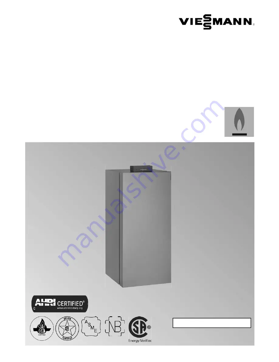
VITOCROSSAL 300

Vitocrossal 300 CU3A 

Models 26, 35, 45, 57, 94, 125, 160, 199

Floor mounted, gas-fired condensing boiler with MatriX gas burner and Lambda Pro control

For operation with natural gas and liquid propane gas

Heating input   19 to 199 MBH


           5.6 to   58 kW

Read and save these instructions

for future reference.

Product may not be exactly as shown

IMPORTANT

H

Summary of Contents for Vitocrossal 300 CU3A

Page 1: ...l 300 CU3A Models 26 35 45 57 94 125 160 199 Floor mounted gas fired condensing boiler with MatriX gas burner and Lambda Pro control For operation with natural gas and liquid propane gas Heating input 19 to 199 MBH 5 6 to 58 kW Read and save these instructions for future reference Product may not be exactly as shown IMPORTANT H ...

Page 2: ...e heating season begins Carbon monoxide Improper installation adjustment service and or maintenance can cause flue products to flow into living space Flue products contain poisonous carbon monoxide gas For information pertaining to the proper installation adjustment service and maintenance of this equipment to avoid formation of carbon monoxide please see subsection entitled Mechanical room and Ve...

Page 3: ...ts and other reproductive harm Always use proper safety clothing respirators and equipment when servicing or working nearby the appliance The state of California has listed the airborne fibers of these materials as a possible cancer hazard through inhalation When handling these materials special care must be applied First aid measures If eye contact occurs flush eyes with water to remove dust If s...

Page 4: ...ng the Heating System 10 Removing the Front Panels 11 Filling Siphon With Water 11 Opening the Control Unit 12 Check Power Supply Connection 12 Start up Wizard 13 Select language 13 Set time and date 13 Select temperature unit 13 Set DHW temperature setpoint 13 Selecting zone circuits 14 Slecting zone circuit type 14 Select fixed setpoint 14 Adjust heating curve 14 Select pump output 15 Confirm pu...

Page 5: ...Check Functioning Safety Valves 29 Check Electrical Connections 30 Check Gas Pipes and Fitting for Leaks 30 Check the Mixing Valve for Obstructions and Leaks 30 Example Layout 1 31 Example Layout 2 35 Example Layout 3 40 Example Layout 4 45 Start up 46 Menu Heating Circuits 47 Functional Description 49 Adjusting the Heating Curves 50 Connecting the Boiler tothe LON System 53 General 55 Boiler 56 D...

Page 6: ...ystem operator ultimate owner where the literature can be found Contact Viessmann for additional copies This product comes with several safety instruction labels attached Do not remove Contact Viessmann immediately if replacement labels are required Initial start up Initial start up must be performed by a qualified heating contractor Proper completion of the Maintenance Record by the heating contr...

Page 7: ...od a battery operated carbon monoxide detector with an alarm shall be installed 2 APPROVED CARBON MONOXIDE DETECTORS Each carbon monoxide detector as required in accordance with the above provisions shall comply with NFPA 720 and be ANSI UL 2034 listed and IAS certified 3 SIGNAGE A metal or plastic identification plate shall be permanently mounted to the exterior of the building at a minimum heigh...

Page 8: ...ter heating systems for space heating and domestic hot water DHW production The Vitocrossal 300 CU3A boiler comes factory set for operation with natural gas For a fuel conversion to liquid propane gas no conversion kit is required Boiler model must be selected based on an accurate heat loss calculation of the building Ensure boiler model is compatible with connected radiation Vitocrossal 300 CU3A ...

Page 9: ...sk WARNING Fire causes a risk of burns and explosion H Shut down the boiler H Close fuel shut off valves H Use a tested fire extinguisher class ABC IMPORTANT The service life of the boiler s exposed metallic surfaces such as the casing and fan housing is directly influenced by proximity to damp and salty marine environments In such areas higher concentration levels of chlorides from sea spray coup...

Page 10: ...e 1 5 to 3 psi 0 1 to 0 2 bar is higher than the pre charge pressure of the diaphragm expansion vessel using the boiler drain fill valve A Max operating pressure 30 psi 2 bar Min operating pressure 14 psi 1 bar Pressure relief valve 30 psi 2 bar 5 Mark the set pressure at temperature and pressure gauge B 6 Return the shutoff valves to their operating position 7 Close boiler drain fill valve A CAUT...

Page 11: ...n with Water 1 Undo fitting A of siphon B remove the siphon and fill it with water Note There is a risk of flue gas escaping if the siphon is not filled with water 2 Refit siphon B 1 Remove the retaining screw and set aside 2 Pull the top of the boiler cover away from the boiler lift off and set aside ...

Page 12: ... in section entitled Additional Information IMPORTANT In Canada all electrical wiring is to be done in accordance with the latest edition of CSA C22 1 Part 1 and or local codes In the U S use the National Electrical Code ANSI NFPA 70 The heating contractor must also comply with both the Standard for Controls and Safety Devices for Automatically Fired Boilers ANSI ASME CSD 1 An external accessories...

Page 13: ... by pressing OK Select temperature unit 1 Select the temperature unit C or F using the 2 Accept by pressing OK Set DHW temperature setpoint 1 Set DHW temperature setpoint with 2 Accept by pressing OK Note if the DHW sensor is installed Select zone circuits During the start up wizard an additional display screen will come up asking for the number of connected zone circuits use to adjust and press O...

Page 14: ...compensated using the outdoor temperature sensor thermostat use to select and press OK Select fixed setpoint For zone circuits with fixed setpoint operation select desired supply water temperature use to adjust and press OK Adjust heating curve Select between slope and shift with and to adjust and press OK Select pump output Assign desired pump output for zone circuit with and press OK ...

Page 15: ...ed zone with fixed set point thermostat will display zone circuit temperature setting Making changes using the start up wizard In the event that an error has been made in the initial set up of the start up wizard or additional system components have been added to the system the start up wizard can be restarted at any time by 1 Press OK and menu simultaneously for approximatelty 4 sec 2 Service Fun...

Page 16: ...ons Setting High Altitude In the factory default setting the boiler is equipped to operate in altitudes of up to 5 000 ft 1 500 m Altitude can be set using coding address 93 in coding level 2 General Coding 11 9 must be set in order to unlock coding 93 93 0 is reserved for altitudes up to 5000 ft 1500 m 93 6 must be set for altitudes from 5000 ft 1500 m to 10000 ft 3000 m Setting back to 93 0 turn...

Page 17: ...ert Fuel Type to LPG Start up Select Gas Type Note the Vitocrossal 300 CU3A boiler is factory set to operate with natural gas See following subsection for conversion instructions to liquid propane gas 1 Ensure that the fuel type listed on the boiler rating plate is the correct type for the installation being attempted 2 Record fuel type in Maintenance Record on page 113 The Vitocrossal 300 CU3A bo...

Page 18: ...sure A CO2 measurement see page 28 must be taken before and after working on gas appliances to eliminate risks to health and to guarantee the satisfactory condition of the system The burner is automatically ignited and starts operation after a safety time has elapsed During initial start up the unit may indicate a fault because of air in the gas supply pipe especially for liquid propane gas After ...

Page 19: ...stem and domestic hot water connections if applicable Ensure all connections are pressure tight Correct any leaks found on fittings pumps valves etc CAUTION Ensure all joints of gas line are pressure tight and that gas valves do not leak when under normal operating pressure use approved leak detection liquid WARNING The gas supply piping must be leak tested before placing the boiler in operation W...

Page 20: ...ANT Viessmann strongly recommends that the heating contractor perform a simplified leak test during boiler start up For this purpose it is sufficient to measure the CO2 concentration of the combustion air in the coaxial gap of the air intake adaptor The vent pipe is considered sufficiently leak proof if a CO2 concentration in the combustion air no higher than 0 2 or an O2 concentration no lower th...

Page 21: ...73 649 18 Vitocrossal 300 CU3A 26 to 199 Service Sequence of Operation and Potential Faults During Each Start up Cycle Function sequence and possible faults For further details on faults see page 86 Start up ...

Page 22: ...pe E and pull air intake adaptor A 5 Undo four nuts B and remove burner F then hook it into its service retainer L Note Prevent damage to the burner Always hook the burner into its service retainer 6 Check burner gasket K for possible damage replace if necessary The burner gasket should be replaced every 2 years Service Placing the Burner Door in the Service Retainer CAUTION To avoid damage to the...

Page 23: ...e the positioning aid on the refractory 8 Insert new burner mesh assembly H with new gasket G and secure with three nuts Torque 3 7 lb ft 5 Nm 9 Fit the fan with the gas valve Torque 3 7 lb ft 5 Nm 1 Check the electrodes for wear and contamination 2 Clean the electrodes with a small brush not with a wire brush or sandpaper 3 Check the electrode gaps If the gaps are not as specified or the electrod...

Page 24: ...heat exchanger surface by thoroughly rinsing with water or solvent free cleaning agents such as citric acid based cleaners Avoid getting the refractory wet during cleaning Note Discoloration of the heat exchanger surface is the normal result of the combustion process It has no impact on the functionality or the longevity of the heat exchanger 4 Use a non metallic brush if necessary with a gentle b...

Page 25: ...connector D with a brush 3 Remove bottom part C of siphon B then clean and refit it 4 Fill siphon B with water and refit with inlet connector D Note There is a risk of flue gas escaping if the siphon is not filled with water 5 Clean the insides of the condensate drain system and the neutralizing system if installed 6 Check the pH value of the condensate with pH measuring strip If the pH value is l...

Page 26: ...n vessel to depressurize the system until the pressure gauge indicates 0 2 If the precharge pressure of the diaphragm expansion vessel is lower than the static system pressure top up with nitrogen until the precharge pressure is raised by 1 5 to 3 psi 0 1 to 0 2 bar 3 Top up your heating system with water until the filling pressure of a cooled system is 1 5 to 3 psi 0 1 to 0 2 bar higher than the ...

Page 27: ...as meter to verify input 1 Ensure all other gas equipment served by the meter is turned off during timing of gas input to the Vitocrossal 300 CU3A boiler 2 Measure the time in seconds it takes for the boiler to use 10 ft 3 of gas Divide 3600 x 10 by the number of seconds and you get the number of ft 3 of gas used per hour Multiply this number by the heating value of the gas to obtain Btu per hour ...

Page 28: ...Then Base load ON appears and the burner operates at its upper heating output Select upper heating output select Full load OFF Then Full load ON appears and the burner operates at its upper heating output Terminate with OK or 4 Measure CO2 and O2 content at boiler vent pipe If the measured values deviated by more than 1 from the ranges for the respective fuel type listed in the right column or in ...

Page 29: ...etween λ 1 24 and 1 44 This range provides for an optimum combustion quality Thereafter the electronic gas valve regulates the required gas volume based on the prevailing gas quality To check the combustion quality the CO2 content or the O2 content of the flue gas is measured The actual values enable the prevailing air factor to be determined The relationship between the CO2 or O2 content and air ...

Page 30: ... leak when under normal operating pressure use approved leak detection liquid WARNING The gas supply piping must be leak tested before placing the boiler in operation WARNING Escaping gas leads to a risk of explosion Check gas equipment for tightness Note For the tightness test use only suitable and approved leak detecting agents and devices Leak detecting agents with unsuitable contents e g nitri...

Page 31: ...10 to 95 C This value must be below the first set DHW temperature DHW tank qR will only be heated by boiler 1 when this set value is no longer achieved by the solar thermal system Matching the control unit to the heating system Subject to the equipment level the control unit must be matched to the system Various system components are recognized automatically by the control unit and the relevant co...

Page 32: ...vice 5673 649 18 32 Example Layout 1 continued Hydraulic installation scheme ID 4605300_1006_01 Note This scheme is a basic example without shut off valves or safety equipment This does not replace the need for local engineering Service ...

Page 33: ...Solar control module type SM1 Collector temperature sensor KOL Solar Divicon Solar circuit pump Circulation pump transfer Automatic thermostatic mixing valve eP eQ Heating circuit I Heating circuit pump heating circuit A1 5 7 zP zW zE zR zT zZ zI zO Accessories Internal extension H1 integrated Connection external safety solenoid valve LPG Central fault message alternative to extension EA1 Extensio...

Page 34: ...Vitocrossal 300 CU3A 26 to 199 Service 5673 649 18 34 Example Layout 1 continued Electrical installation diagram Service ...

Page 35: ...perature for tank heating to be reached In this case DHW tank qP or qR and heating circuit with mixing valve rP are heated simultaneously DHW heating by the solar thermal system Solar circuit pump wE starts and DHW tank qR is heated up if the temperature differential between collector temperature sensor wQ and tank temperature sensor qT exceeds the start temperature differential Pump wE is stopped...

Page 36: ...vice 5673 649 18 36 Example Layout 2 continued Hydraulic installation scheme ID 4605301_1006_02 Note This scheme is a basic example without shut off valves or safety equipment This does not replace the need for local engineering Service ...

Page 37: ...r collectors Solar control module type SM1 Collector temperature sensor KOL Solar Divicon Solar circuit pump Circulation pump transfer Automatic thermostatic mixing valve eP eQ Heating circuit I Heating circuit pump heating circuit A1 rP rR rQ rT rR rQ rT rW rE Heating circuit II Extension kit for one heating circuit with mixing valve M2 Components Supply temperature sensor M2 contact temperature ...

Page 38: ...entral fault message alternative to extension EA1 Extension EA1 integrated External safety solenoid valve for LPG Central fault message External hook up External blocking External demand External heating program changeover External set value 0 to 10V Vitotrol 200A Vitotrol 300A KM BUS distributor for several KM BUS participants KM BUS participant Extension EA1 7 Vitotrol 200A zT Vitotrol 300A zZ S...

Page 39: ...39 5673 649 18 Vitocrossal 300 CU3A 26 to 199 Service Example Layout 2 continued Electrical installation diagram Service ...

Page 40: ...for tank heating to be reached In this case DHW tank qP or qR and heating circuit with mixing valve rP and tP are heated simultaneously DHW heating by the solar thermal system Solar circuit pump wE starts and DHW tank qR is heated up if the temperature differential between collector temperature sensor wQ and tank temperature sensor qT exceeds the start temperature differential Pump wE is stopped a...

Page 41: ...A 26 to 199 Service Example Layout 3 continued Hydraulic installation scheme ID 4605302_1006_01 Note This scheme is a basic example without shut off valves or safety equipment This does not replace the need for local engineering Service ...

Page 42: ...ntrol module type SM1 Collector temperature sensor KOL Solar Divicon Solar circuit pump Circulation pump transfer Automatic thermostatic mixing valve eP eQ Heating circuit I Heating circuit pump heating circuit A1 rP tP rQ tQ rW tW rT tT rQ tQ rW tW rT tT tE rR tR Heating circuit II and III Extension kit for one heating circuit with mixing valve M2 M3 Components Supply temperature sensor M2 M3 con...

Page 43: ...entral fault message alternative to extension EA1 Extension EA1 integrated External safety solenoid valve for LPG Central fault message External hook up External blocking External demand External heating program changeover External set value 0 to 10V Vitotrol 200A Vitotrol 300A KM BUS distributor for several KM BUS participants KM BUS participant Extension EA1 7 Vitotrol 200A zT Vitotrol 300A zZ S...

Page 44: ...Vitocrossal 300 CU3A 26 to 199 Service 5673 649 18 44 Example Layout 3 continued Electrical installation diagram Service ...

Page 45: ...t heating circuits DHW production 3 zone circuits Legend A Vitocrossal 300 CU3A boilers B DHW storage tank C DHW pump output 21 D DHW recirculation pump output 28 20 E Thermostat zone circuits 1 2 3 dry contact F Zone circuit 1 output 157 G AM1 extension module accessory H Zone circuit 2 output A1 AM1 extension module I Zone circuit 3 output A2 AM1 extension module ...

Page 46: ...uge The heating system pressure is too low if the indicator is below 14 psi In this case top up with water or notify your local heating contractor 2 For room air dependent operation Check that the ventilation opening of the installation room are open and unrestricted Note With room air dependent operation the combustion air is drawn from the boiler room 3 Open the gas shut off valve Note Ask your ...

Page 47: ...ntly used settings for the heating circuit shown in the header Press the following keys to set room temperature for the required value OK to confirm Heating programs 9 Standby mode with frost protection monitoring w Only DHW w z Heating and DHW Press the following keys for the required heating program OK to confirm Note 2 minutes after any setting has been made the display automatically reverts to...

Page 48: ...rcuit selected in the standard menu To change this refer to the Operating Instructions e Frost protection monitoring s Central heating with standard temperature m Central heating with reduced temperature Party mode enabled Economy mode enabled In conjunction with a solar thermal system Solar circuit pump running A Burner in operation Messages Service message Fault message Extended menu In the exte...

Page 49: ...0ºC during the regular time schedule You can activate this function by selecting a switching period for the fourth time phase See Operating Instructions The temperature setpoint for this function is adjustable in coding address 58 Space heating mode For operation with heating circuits the control unit calculates a boiler water setpoint temperature based on the outdoor or room temperature where a r...

Page 50: ...Shift 6 Select heating curve according to the system requirements The heating curves illustrate the relationship between the outdoor temperature and the boiler water or supply temperature To put it simply the lower the outside temperature the higher the boiler water or supply temperature The room temperature again depends on the boiler water or the supply temperature Note If the heating system inc...

Page 51: ...perature C Set room temperature D Heating circuit pump OFF E Heating circuit pump ON Adjustment of the standard room temperature Refer to the Operating Instructions Reduced room temperature Example 2 Adjustment of reduced room temperature from 41 F to 57 F 5 C to 14 C Legend A Boiler water temperature or supply temperature B Outdoor temperature C Set room temperature D Heating circuit pump OFF E H...

Page 52: ...ture the boiler water or supply temperature will be raised in accordance with the selected heating curve The boiler water or supply temperature can be automatically increased The value and duration of the additional increase of the set boiler water or supply temperature can be adjusted in coding addresses FA and FB Legend A Heating curve for operation with standard room temperature B Heating curve...

Page 53: ...C 3 Note One heating circuit can be allocated to the Vitotrol 200A Up to three heating circuits can be allocated to the Vitotrol 300A If the heating circuit allocation is later cancelled reset coding address A0 for this heating circuit to 0 fault message BC BD BE Connecting the Boiler to the LON System Single boiler system with Vitotronic 200 H and Vitocom 100 LAN 1 example Set the LON participant...

Page 54: ...ode 79 0 Device is fault manager Control unit transmits the time Code 7B 1 The control unit receives the time Set code 81 3 The control unit receives the time Set code 81 3 Device receives the time Control unit transmits outside temperature Set code 97 2 Control unit receives outside temperature Set code 97 1 Control unit receives outside temperature Set code 97 1 LON participant fault monitoring ...

Page 55: ...lve heating circuit 1 one heating circuit with mixing valve heating circuit 2 and one heating circuit with mixing valve heating circuit 3 without DHW heating code is adjusted automatically 10 3 One heating circuit without mixing valve heating circuit 1 one heating circuit with mixing valve heating circuit 2 and one heating circuit with mixing valve heating circuit 3 with DHW heating code is adjust...

Page 56: ...gram for DHW heating possible Lock out controls 8F 0 Operation in the standard menu and extended menu enabled Note The respective code is only activated when you exit the service menu 8F 1 Operation in standard menu and extended menu blocked Emissions test mode can be enabled 8F 2 Operation enabled in the standard menu and blocked in the extended menu Emissions test mode can be enabled Set supply ...

Page 57: ...hes 140 F 60 C maximum DHW tank temp 08 10 to 08 90 Set DHW temperature adjustable from 50 F to 194 F 10 C to 90 C Stagnation time reduction 0A 5 To protect the system components and heat transfer medium the speed of the solar circuit pump is reduced when the differential between the actual DHW tank temperature and the set DHW tank temperature is less than 5 K 0A 0 Stagnation time reduction disabl...

Page 58: ...emperature This value is based on the actual outside temperature and a time constant which takes the cooling down of an average building into consideration Coding in the factory setting Possible change Priority DHW heating A2 2 DHW tank priority applicable to heating circuit pump and mixing valve A2 0 Without DHW tank priority applied to heating circuit pump and mixing valve A2 1 DHW tank priority...

Page 59: ...e from 1 to 15 1 Short idle period 15 Long idle period Room temperature hook up B0 0 Only with heating circuit with mixing valve and remote control Heating mode and reduced mode B0 1 Heating mode weather compensated Reduced mode with room temperature hook up B0 2 Heating mode with room temperature hook up Reduced mode B0 3 Heating mode reduced mode with room temperature hook up Economy function ro...

Page 60: ...d room temperature or Standby mode D5 1 The external heating program changeover changes to Constant operation with standard room temperature subject to coding address 3A 3B and 3C Ext heating program changeover to heating circuit D8 0 No heating program changeover via extension EA1 D8 1 Heating program changeover via input DE1 at extension EA1 D8 2 Heating program changeover via input DE2 at exten...

Page 61: ...ctions F9 10 to F9 60 Temperature limit for raising the set room temperature to the value selected for standard mode adjustable from 50 F to 76 F 10 C to 60 C Set supply temperature heating circuit FA 20 Raising the set boiler water temperature or the set supply temperature when changing from operation with reduced room temperature to operation with standard room temperature by 20 See operating in...

Page 62: ...heir factory setting Select Standard setting in Coding level 2 Note This also resets codes at coding level 1 Value address 00 System type Description 1 1 One heating circuit without mixing valve heating circuit 1 without DHW heating 2 1 One heating circuit without mixing valve heating circuit 1 with DHW heating code is adjusted automatically 3 2 One heating circuit with mixing valve heating circui...

Page 63: ...adjustable from 68ºF to 185ºF 20ºC to 85ºC limited by boiler specific parameters 2D 0 DO NOT ADJUST 32 1 DO NOT ADJUST 32 0 33 1 Function output A1 at extension AM1 Heating circuit pump 33 0 Function output A1 DHW recirculation pump 33 2 Function output A1 Circulation pump for DHW tank heating 33 3 No function 33 4 No function 33 5 Zone circuit pump 1 33 6 Zone circuit pump 2 33 7 Zone circuit pum...

Page 64: ...mp push button function DHW recirculation pump runtime adjustment Coding address 3D 3A 7 Input zone circuit 1 constant 3A 8 Input zone circuit 1 weather compensated 3B 0 Function input DE2 at extension EA1 Not assigned 3B 1 Function input DE2 Heating program changeover 3B 2 Function input DE2 External demand with set supply temperature Supply temperature setting Coding address 9B Internal circulat...

Page 65: ...ump runtime for brief operation 5 minutes 3D 1 to 3D 60 DHW recirculation pump runtime adjustable from 1 to 60 minutes 3E 0 Internal circulation pump stays in control mode at signal External blocking 3E 1 Internal circulation pump stops at signal External blocking 3E 2 Internal circulation pump starts at signal External blocking 3F 0 Internal circulation pump stays in control mode at signal Extern...

Page 66: ... 54 1 With Vitosolic 100 automatic recognition 54 2 With Vitosolic 200 automatic recognition 54 3 With solar control module SM1 without auxiliary function automatic recognition 54 4 With solar control module SM1 with auxiliary function e g central heating backup automatic recognition 6E 50 No correction of measured outside temperature 6E 0 to 6E 100 Outside correction in 0 1 K steps 0 to 49 5 K to...

Page 67: ...intertime changeover 81 2 Use of the radio clock receiver automatic recognition 81 3 With LON communication module The control unit receives the time 82 0 Operation with natural gas 82 1 Operation with LPG only adjustable if coding address 11 9 has been set 88 0 Temperature display in C Celsius 88 1 Temperature display in F Fahrenheit 8A 175 Do not adjust 8F 0 Operation in the standard menu and ex...

Page 68: ... communication module Viessmann system number in conjunction with monitoring several systems via Vitocom 300 98 1 to 98 5 System number adjustable from 1 to 5 99 0 DO NOT ADJUST 9A 0 DO NOT ADJUST 9B 70 Set supply temperature for external demand 158 F 70 C 9B 0 to 9B 127 Set supply temperature for external demand adjustable from 32 F to 260 F 0 C to 127 C limited by boiler specific parameters 9C 2...

Page 69: ...JUST 14 1 DO NOT ADJUST 15 1 DO NOT ADJUST 21 0 No service interval hours run selected 21 1 to 21 100 Number of hours run before the burner should be serviced is adjustable from 100 to 10 000 h One adjusting step K 100 h 23 0 No time interval for burner service 23 1 to 23 24 Interval adjustable from 1 to 24 months 24 0 No Service display 24 1 Service display the address is automatically set and mu...

Page 70: ...ler 5b 1 DHW tank connected downstream of the low loss header 5E 0 Circulation pump for DHW tank heating stays in control mode at signal External blocking 5E 1 Circulation pump for DHW tank heating stops at signal External blocking 5E 2 Circulation pump for DHW tank heating starts at signal External blocking 5F 0 Circulation pump for DHW tank heating stays in control mode at signal External demand...

Page 71: ...ified by the boiler coding card 6F 0 to 6F 100 Maximum output for DHW heating adjustable from minimum output to 100 71 0 DHW recirculation pump ON in accordance with the time program 71 1 OFF during DHW heating to first set value 71 2 ON during DHW heating to first set value 72 0 DHW recirculation pump ON in accordance with the time program 72 1 OFF during DHW heating to second set value 72 2 ON d...

Page 72: ...l 03 10 The temperature differential between the collector temperature and actual DHW tank temperature is regulated to 10 K 03 5 to 03 20 The differential temperature control between collector temperature and actual DHW tank temperature can be adjusted from 5 to 20 K 04 4 Controller amplification of the speed control 4 K 04 1 to 04 10 Controller amplification adjustable from 1 to 10 K 05 10 Minimu...

Page 73: ...ection function switched on not required with Viessmann heat transfer medium 0C 1 t monitoring switched on No flow rate captured in the solar circuit or flow rate too low 0C 0 t monitoring switched off 0D 1 Night circulation monitoring switched on Unintentional flow rate is captured in the solar circuit e g at night 0D 0 Night circulation monitoring switched off 0E 1 Calculation of solar yield wit...

Page 74: ...rature is exceeded at the collector temperature sensor 12 0 Minimum collector temperature function switched off 12 1 to 12 90 Minimum collector temperature adjustable from 34 F to 194 F 1 C to 90 C 20 0 No extended control functions enabled 20 1 Auxiliary function for DHW heating 20 2 Differential temperature control 2 20 3 Differential temperature control 2 and auxiliary function 20 4 Differentia...

Page 75: ...le from 0 to 100 K 26 1 Priority for DHW tank 1 with alternate heating Only when setting code 20 9 26 0 Priority for DHW tank 1 without alternate heating 26 2 Priority for DHW tank 2 without alternate heating 26 3 Priority for DHW tank 2 with alternate heating 26 4 Alternate heating without priority for one of the DHW tank 27 15 Alternate heating time 15 minutes The DHW tank without priority is he...

Page 76: ... 37 4 to 60 8 F to 3 to 16 C Coding in the factory setting Possible change A0 0 Without remote control A0 1 With Vitotrol 200A automatic recognition A0 2 With Vitotrol 300A automatic recognition A1 0 All possible settings at the remote control can be accessed A1 1 Only party mode can be set at the remote control only for Vitotrol 200A A2 2 DHW tank priority applicable to heating circuit pump and m...

Page 77: ...K 2 AT RTset 4 K 3 AT RTset 3 K 4 AT RTset 2 K 5 AT RTset 1 K 6 AT RTset 7 to 15 AT RTset 1 K to AT RTset 9 K Coding in the factory setting Possible change A6 36 Extended economy function disabled A6 5 to A6 35 Extended economy function enabled i e the burner and heating circuit pump will stop and the mixing valve close at a variable value adjustable between 41 F and 95 F 5 C and 35 C plus 1 8 F 1...

Page 78: ...Without pump idle time A9 1 to A9 15 With pump idle time adjustable from 1 to 15 B0 0 With remote control Heating mode reduced mode only change the code for the heating circuit with mixing valve B0 1 Heating mode weather compensated Reduced mode with room temperature hook up B0 2 Heating mode with room temperature hook up Reduced mode weather compensated B0 3 Heating mode reduced mode with room te...

Page 79: ...ation with standard room temperature subject to coding address 3A 3B and 3C D6 0 Heating circuit pump stays in control mode at signal External blocking D6 1 Heating circuit pump stops at signal External blocking subject to coding addresses 3A 3B and 3C D6 2 Heating circuit pump starts at signal External blocking subject to coding addresses 3A 3B and 3C D7 0 Heating circuit pump stays in control mo...

Page 80: ... party mode or external heating program changeover via push button 8 h 1 F2 0 No time limit for party mode 1 F2 1 to F2 12 Time limit adjustable from 1 to 12 h 1 F5 12 Run on time of the boiler circuit pump in heating mode 12 minutes F5 0 No run on time for the circulation pump in the heating circuit connection set F5 1 to F5 20 Run on time of the circulation pump in the heating circuit connection...

Page 81: ...40 Heating curve level adjustable from 13 to 40 Zone circuit 1 68 14 Heating curve slope 1 4 68 2 to 68 35 Heating curve slope adjustable from 0 2 to 3 5 Zone circuit 2 69 0 Heating curve level 0 69 13 to 69 40 Heating curve level adjustable from 13 to 40 Zone circuit 2 6A 14 Heating curve slope 1 4 6A 2 to 6A 35 Heating curve slope adjustable from 0 2 to 3 5 Zone circuit 3 6B 0 Heating curve leve...

Page 82: ...ing and resetting service Press OK to acknowledge a service message Note An acknowledged service message that was not reset reappears the following Monday After a service has been carried out reset service 1 Press OK and simultaneously for approx 4 sec 2 Service functions 3 Service reset Note The selected service parameters for hours run and time interval restart at 0 Service menu overview Service...

Page 83: ...pants Maximum demand temperature 3 0 Software version Programming unit Software version Mixing valve extension 0 No mixing valve extension 0 Software version LON module 0 4 Software version Burner control unit Type Burner control unit Appliance type 5 0 0 0 0 0 6 Number of LON participants Check digit Max output Details in 7 Heating circuit A1 without mixing valve Heating circuit M2 with mixing va...

Page 84: ... circuit with mixing valve Htg circ pump HC3 Start Heating circuit pump output enabled extension to heating circuit with mixing valve Mixing valve HC3 Open Mixing valve open output enabled extension to heating circuit with mixing valve Mixing valve HC3 Close Mixing valve closed output enabled extension to heating circuit with mixing valve Outp int exten H1 Start Output at internal extension H1 ena...

Page 85: ...he fault message will be re displayed the following day and the fault output device restarted Calling up acknowledged faults Select Fault in the standard menu The current faults will be displayed in a list Calling up fault codes from the fault memory fault history The 10 most recent faults including resolved ones are saved and can be called up Faults are sorted by date 1 Press OK and simultaneousl...

Page 86: ...ture sensor see page 94 4C Mixing valve closes Supply temperature sensor cable broken circuit 3 with mixing valve Check supply temperature sensor see page 94 50 No DHW heating Short circuit on DHW tank temperature sensor Check the DHW sensor see page 94 58 No DHW heating Tank temperature sensor cable broken Check the sensor see page 94 90 Control mode Short circuit temperature sensor Check sensor ...

Page 87: ...on fault programming unit internal Check connections and replace programming unit if required B5 Control mode factory default setting Internal fault Replace the control unit B7 Burner blocked Boiler coding card missing faulty or incorrect boiler coding card Plug in boiler coding card or replace if faulty B8 Burner blocked Flue gas temperature sensor cable broken Check flue gas temperature sensor s...

Page 88: ...n module C1 Control mode Communication fault extension EA1 Check connections Without extension EA1 set code 35 0 C2 Control mode Communication fault solar control unit or Vitosolic Check solar control or Vitosolic C4 Control mode Communication fault Open Therm extension Check Open Therm extension C7 Control mode max pump speed Communication fault variable speed circulation pump heating circuit wit...

Page 89: ...setting see page 94 DE Control mode without room influence Room temperature sensor cable broken heating circuit 2 with mixing valve Check the room temperature sensor heating circuit 2 and the remote control settings see page 94 DF Control mode without room influence Room temperature sensor cable broken heating circuit 3 with mixing valve Check room temperature sensor for heating circuit 3 and remo...

Page 90: ... R EA Burner in a fault mode The ionization current lies outside the permissible range during calibration deviation from previous level too great Check flue system remedy flue gas recirculation if required In open flue mode prevent very dusty conditions for the combustion air Press reset button R Following several unsuccessful reset attempts replace boiler coding card and press reset button R EB B...

Page 91: ...de Press reset button R Check combustion air common combustion air intake for blockages replace air intake adaptor F0 Burner blocked Internal fault Replace the control unit F1 Burner in a fault mode Maximum flue gas temperature exceeded 230ºF 110ºC limit Check heating system fill level Bleed air from system Check circulation pump Check boiler water temperature sensor and cable Press reset button R...

Page 92: ...state and additional fault B7 is displayed Boiler coding card is missing Insert the boiler coding card Press reset button R Replace control unit if fault persists Burner in a fault state Fault burner control unit Check ignition electrodes and connecting cables Check whether a strong interference EMC field exists near the appliance Press reset button R Replace control unit if fault persists FE Burn...

Page 93: ... the curve values disconnect the wires at the sensor and repeat test on the sensor itself 4 Depending on the result replace the lead or the outdoor temperature sensor Sensor type NTC 10 kΩ Checking the outdoor temperature sensor 1 Remove the screws from the top panel and set aside 2 Slide the top panel to the rear of the boiler and lift up 3 Remove the retaining nuts from the control connection co...

Page 94: ...e deviation Temperature sensors Resistance in k Ohms Troubleshooting Corrective Action continued Temperature sensors Resistance in k Ohms Checking the boiler temperature sensor 1 Pull plug and measure the resistance 2 Check the sensor resistance and compare it with the curve 3 Replace the sensor in the case of severe deviation 4 Release the strain relief on the sensor well and pull the sensor out ...

Page 95: ... the permissible flue gas temperature is exceeded Reset the interlock after the flue system has cooled down by pressing reset button R 1 Pull the leads from flue gas temperature sensor A 2 Check the sensor resistance and compare it with the curve 3 Replace the sensor in the case of severe deviation Checking the boiler fuse 1 Switch off the power 2 Remove top panel and cover see page 93 3 Check fus...

Page 96: ...on interface C Fuse F1 Integrate EA1 module D Fuse F2 Power pump connection interface E Fuse F1 Power pump connection interface Checking the electrical connect module fuse 1 Switch off the power 2 Remove front panel and cover see page 93 3 Check fuse F1 and F2 of the power pump connection interface 4 Check fuse F1 and F2 of the integrate EA1 module ...

Page 97: ...ng in the wrong direction or the mixing valve set is incorrectly fitted Checking the rotational direction of the mixing valve motor After being switched on the boiler implements a self test During this the mixing valve is opened and closed again WARNING Electric shock hazard indicates an imminently hazardous situation which if not avoided may result in loss of life serious injury or substantial pr...

Page 98: ...DE1 Digital input 1 DE2 Digital input 2 DE3 Digital input 3 0 10V 0 10V input fÖ Power supply fÖA A Power supply for additional accessories aBJ Central fault message feed pump DHW recirculation pump potential free aVG KM BUS Function Description Refer to main wiring diagram on page 101 ...

Page 99: ... duration of the changeover is set via coding address F2 in the Heating circuit group Effect of the external blocking function on the pumps The effect on the respective heating circuit pump is selected in coding address D6 in the Heating circuit group The effect on a circulation pump for DHW tank heating is selected in coding address 5E in the DHW group Effect of the external demand function on th...

Page 100: ... input DE2 D8 2 Changeover via input DE3 D8 3 Heating program changeover Coding Input DE1 3A 1 Input DE2 3B 1 Input DE3 3C 1 External blocking The External blocking and External blocking and fault message input functions are connected via extension EA1 There are 3 inputs available at extension EA1 DE1 to DE3 The function is selected via the following codes The effect on the internal circulation pu...

Page 101: ...ON Label all wires prior to disconnection when servicing controls Wiring errors can cause improper and dangerous operation Verify proper operation after servicing If any of the original wires as supplied with the appliance must be replaced it must be replaced with the exact equivalent Only one function connection may be assigned to each connection ...

Page 102: ... temperature Sensor 20 Boiler Pump 21 DHW Pump 28 20 Programmable Pump Output zone circuit pump output 35 Gas Valve 40 Power Supply 40A Accessory Power Output 54 Ignition Transformer 96 Powered Accessory Connection 100 Fan Motor 100A Fan Motor Control 111 Not Used 145 KM BUS 147 Pump Modulation Output 0 10VDC Multi Powered Accessory Connection 156A Switched Output F2 156B Switched Output F1 DE1 Di...

Page 103: ...18 Vitocrossal 300 CU3A 26 to 199 Service Additional Information Fitting the Front Panel 1 Place the front cover onto the locating pegs 2 Push the top of the panel in place 3 Secure in place with the retaining screw ...

Page 104: ... 1 5 seconds If the flame is not established after 3 trials the burner will lock out and will require a manual reset Controller required time for flame stabilization Phase 6 Burner modulation operation or calibration At the end of the flame stabilization period 4 5 seconds a release for modulation occurs and the burner temperature controller will take over from the flame safeguard Forced shutdown ...

Page 105: ... Serial Number A when ordering replacement parts Order replacement components from your Viessmann distributor Overview of Assemblies A Rating Plate and Serial Number B Enclosure Assembly C Control Assembly D Boiler Assembly E Burner Assembly F Other Parts see your Viessmann distributor Other Parts not illustrated 0300 Installation Set 1 0404 Parts List Vitocrossal boiler 0410 Conversion kit NG LP ...

Page 106: ...osure Assembly 0001 Spring clip for insulation set of 4 0002 Cover edge molding 0003 Accessory pack front panel hardware 0004 Insulation blanket 0005 Accessory pack insulation 0006 Top panel rear 0007 Front panel 0008 Top panel front 0009 Mid panel control 0010 Insulation blanket rear 0011 Insulation blanket front 0012 Accessory pack mounting fasteners set of 4 0013 Side panel left right 0014 Moun...

Page 107: ... B30 0010 Accessory pack plug 20 28 40 21 96 0011 Harness X8 X9 Ionization 0012 Harness gas valve 35 0013 Harness ignition transformer 54 PE 0014 Harness fan 100 0015 Harness expanded functions 0016 Harness pumps 20 21 96 0017 Harness power 40 40A 0018 Harness KM BUS 145 0019 Harness X7 0020 Sensor 1 outdoor NTC 0021 Sensor 5 DHW immersion NTC 0022 Sensor 3 boiler NTC 0023 Circuit board expanded f...

Page 108: ...y 0001 Sensor well G L 150 with clip 0002 Test port cap set of 2 0003 Leveling bolt each 0004 Clamp for fresh air hose D70 90 set of 2 0005 Gasket for flue gas collector 0006 Sensor 15 flue gas 0007 Condensate siphon 0008 Gasket for flue gas 0009 Air Intake adaptor 0010 Flue gas collector with gaskets and sensor 0011 Bracket for flue gas collector 0012 Fresh air hose flexible D80 0013 Gasket D65 s...

Page 109: ...tion electrode 0006 Gasket for ionization electrode 0007 Gasket for NG LP set of 5 0008 Orifice 0009 Connection pipe 1 NG LP with gaskets 0010 Adaptor CES10 0011 Gasket for radial fan 0012 Gasket for burner mesh 0013 Turbulator disc 0014 Accessory pack for burner parts 0015 Ignition module 0016 Gas valve CES10 with gasket 0017 Radial fan NRG118 with gaskets 0018 Sight glass 0019 Connection pipe 2 ...

Page 110: ...ut off base e in 0302 Hex bushing c in x e in 0303 Tee c in 0304 Pressure relief valve 30 psig 0305 Nipple c in x 1b in 0306 90 Street elbow c in 0307 Nipple c in x 4 in 0308 Reduction coupling 1a in x c in 0309 Temperature and pressure gage 1 0311 Reduction tee 1a in x 1a in x b in 0312 Gas ball valve c in 0313 Combustion air intake adaptor CPVC 3 in 0314 Reduction tee 1 in x 1 in x c in 0315 Sed...

Page 111: ...13 0 49 18 8 71 18 8 71 Max operating pressure at 210ºF 99ºC psig bar 30 2 30 2 30 2 30 2 Boiler water temperature Adjustable high limit AHL range space heating steady state DHW production Fixed high limit FHL ºF ºC ºF ºC ºF ºC 68 194 20 90 194 90 210 99 68 194 20 90 194 90 210 99 68 194 20 90 194 90 210 99 68 194 20 90 194 90 210 99 Boiler connections Boiler heating supply and return Pressure rel...

Page 112: ...on 6 Ø in mm 3 80 3 80 4 110 4 110 Combustion air supply connection outer Ø in mm 3 80 3 80 3 80 3 80 Sound Rating A scale at maximum input at minimum input dB dB 48 32 55 33 53 33 58 33 Standby losses 7 BTU hr W hr 1128 330 1000 292 1120 328 995 291 4 Measured flue gas temperature with a combustion air temperature of 68 F 20 C 5 Based on maximum input rate 6 For side wall vent installations coaxi...

Page 113: ...113 5673 649 18 Vitocrossal 300 CU3A 26 to 199 Service Additional Information Maintenance Record ...

Page 114: ...y result in a fire or explosion D Do not use this appliance if any part has been under water Immediately call a qualified service technician to inspect the appliance and to replace any part of the control system and any gas control which has been under water OPERATING INSTRUCTIONS 1 STOP Read the safety information above on this label 2 Set thermostat or other operating control to lowest setting 3...

Page 115: ...115 5673 649 18 Vitocrossal 300 CU3A 26 to 199 Service ...

Page 116: ...Technical information subject to change without notice Printed on environmentally friendly recycled and recyclable paper Vitocrossal 300 CU3A 26 to 199 Service 5673 649 18 ...

Reviews: