
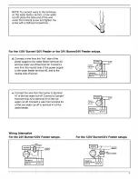
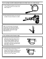

For the 24V Burner/24V Feeder setups.
BURNER
101A-24
120 VAC
SUPPLY
24V TRANSFORMER
(101-24V-48)
1
2
3
4
N
H
24V
69
c.
Connect the "hot" wire from the boiler trans-
former to terminal #2 of the low water cut-off.
Connect the "hot" side of the water feeder
transformer to terminal #3 of the low water
cut-off. Connect the neutral side of the boiler
transformer to the burner. Using a wire nut,
connect the neutral side of the water feeder
transformer to the water feeder.
BURNER
101A-24
120 VAC
SUPPLY
24V TRANSFORMER
(101-24V-48)
1
2
3
4
N
H
24V
d.
Connect the wire from the burner to terminal
#1 of the low water cut-off. Connect a wire
from terminal #4 of the low water cut-off to the
remaining wire in the water feeder. Wire nut
together.
BURNER
101A
120 VAC
SUPPLY
N
H
24V
1
2
3
4
69
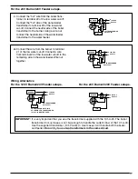
Wiring Alternative
For the 120V Burner/24V Feeder setups.
For the 24V Burner/120V Feeder setups.
BURNER
101A-24
120 VAC
SUPPLY
24V TRANSFORMER
(101-24V-48)
TO AVOID DAMAGE TO 101A
SOLENOID COIL, TRANSFORMER
101-24V-48 MUST BE USED.
N
H
1
2
3
4
69
11
IMPORTANT:
It is very important that you use the transformer supplied with the 101-A-24. The boiler
transformer in most cases is not big enough to handle the current draw of the 101-A-24.
Use the supplied transformer (101-24-48). In most cases it will handle both the boiler
and feeder.
Do not try to use two transformers in the same circuit.
Содержание McDonnell & Miller 67 Series
Страница 1: ...INSTRUCTION MANUAL MM 201H Series 67 and 767 Low Water Cut Offs For Steam Boilers...
Страница 9: ......


