background image

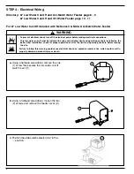
NOTE: To connect wires to the terminals
on the burner, or low water cut-off, place
the bare end of the wire under the terminal
screw and tighten the screw with a flat-
head screwdriver. On the 101-A water
feeder use wire nuts.

Y

a.

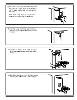
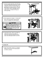
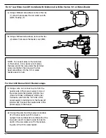
Using a flathead screwdriver, remove the one
(1) screw that secures the low water cut-offs
switch housing (Y).

BB

b.

Using a flathead screwdriver, remove the two

(2) screws that secure the feeder cover (BB).

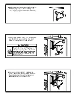
For 67 Low Water Cut-Off Installed with McDonnell & Miller Series 101-A Water-Feeder

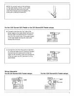
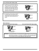
For the 120V Burner/120V Feeder setups.

BURNER

120 VAC
SUPPLY

1

2

3

4

N

H

101A

69

c.

Using a wire nut, connect a wire from the
neutral side of the power supply to one of
the wires inside the feeders junction box.
(Does not make a difference which one).
Connect a wire from the "hot" side of the
power supply to terminal #2 of the Series 67
junction box. Connect the neutral side of the
power supply to the burner.

BURNER

120 VAC
SUPPLY

1

2

3

4

N

H

101A

d.

Connect the wire from the burner to terminal

#1 of the low water cut-off. Connect a
"jumper" from terminal #2 to terminal #3 of the
low water cut-off. Connect a wire from termi-
nal #4 of the low water cut-off to the remain-
ing wire in the 101A water feeder.

10

Содержание McDonnell & Miller 67 Series

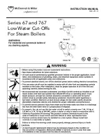
Страница 1: ...INSTRUCTION MANUAL MM 201H Series 67 and 767 Low Water Cut Offs For Steam Boilers...

Страница 2: ...C For Series 67 The elevation of the control A is already determined by the location of the gauge glass tappings B C on the boiler The horizontal cast line D should be located at or above the boiler m...

Страница 3: ...ntrol and tighten a 2 13mm NPT pipe plug G provided into the tapping on the bottom of the control body A Tighten the pipe plug to 31 ft lb 42 N m A F G When using the tape sealant on the external thre...

Страница 4: ...install the pipe tee P provided onto the nipple M in the upper tapping N Tighten to 31 ft lb 42 N m N M P f Using an adjustable wrench install 1 2 13mm NPT compression fitting base U into the upper te...

Страница 5: ...sing a pencil mark the tubing Q for proper insertion into the compression fitting K Remove the tubing Q and using the tube cutter cut the tubing to its proper length Q K 5 i Using two 2 pipe wrenches...

Страница 6: ...down valve U and tighten to 47 ft lb 64 N m A W m Hang the blow down card W enclosed as close to the control A as possible or remove the protective backing and affix the card on the boiler jacket clo...

Страница 7: ...lb 148 N m d Hang a blow down card W enclosed as close to the control A as possible or remove the protective backing and affix the card on the boiler jacket close to the control To prevent burning or...

Страница 8: ...peration of all of the limit and operating controls before leaving the site Failure to follow this warning could cause electrical shock an explosion and or a fire which could result in property damage...

Страница 9: ......

Страница 10: ...der For the 120V Burner 120V Feeder setups BURNER 120 VAC SUPPLY 1 2 3 4 N H 101A 69 c Using a wire nut connect a wire from the neutral side of the power supply to one of the wires inside the feeders...

Страница 11: ...nal 1 of the low water cut off Connect a wire from terminal 4 of the low water cut off to the remaining wire in the water feeder Wire nut together BURNER 101A 120 VAC SUPPLY N H 24V 1 2 3 4 69 Wiring...

Страница 12: ...ment chemicals PROCEDURE 1 Blow down the low water cut off when the water level is at its normal level and the burner is on Fully open the blow down valve and observe the water level fall in the gauge...

Отзывы: