3
Resilient separator
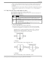
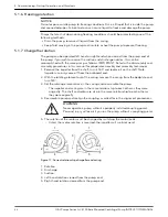
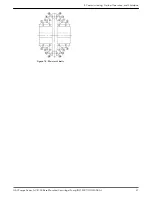
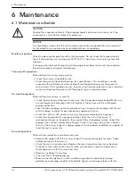
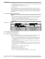
Figure 7: Pump alignment via dial indicator
d) Set the dial to zero.
e) Rotate both coupling halves together and make sure that the index lines remain
matched.
f) Reposition the equipment until the offset is within the permissible value.
2. Check the parallel misalignment:
a) Mount the dial indicator base to one coupling half, or shaft.
b) Position the dial indicator button on the outside diameter of the opposite coupling
half.
c) Set the dial to zero.
d) Rotate both coupling halves together and make sure that the index lines remain
matched.
e) Reposition the equipment until the offset is within the permissible value.
f) Assemble coupling. Tighten all bolts and set screw(s). It may be necessary to repeat
steps for a final check.
For single element couplings, a satisfactory parallel misalignment is .004” T.I.R., while a
satisfactory angular misalignment is .004” T.I.R. per inch of radius R.
4.2.4 Final alignment
You cannot perform the final alignment until you initially operate the pump long enough
to reach operating temperature. When the pump reaches the normal operating
temperature, then secure the pump and re-check the alignment. Make sure that you
compensate for temperature accordingly.
NOTICE:
Elastomeric couplings are specifically designed to accommodate angular shaft
misalignment, as well as parallel offset of the pump and motor shafts. However, the
amount of the offset and/or misalignment depends on the style of the applied flexible
coupling. If you do not correct this coupling misalignment, there is a significant impact on
the overall life of the mechanical seals and the bearings of the pump.
4.2.5 Optional alignment procedure
If desired, the pump and motor feet can be doweled to the base after final alignment is
complete. This should not be done until the unit has been run for a sufficient length of
time and alignment is with the tolerance. See doweling section.
NOTE: Pump may have been doweled to base at factory.
4.2.6 Dowel the pump and driving unit
1. Drill holes through diagonally opposite feet and into the base. Holes must be of a
diameter 1/64 inch less then the diameter of the dowel pins.
2. Ream the holes in feet and base to the proper diameter for the pins (light push fit).
Clean out the chips.
3. Insert pins to be approximately flush with feet.
4 Installation
G&L Pumps Series A-C 8100 Base Mounted Centrifugal Pump INSTRUCTION MANUAL
19
Содержание G&L A-C 8100 Series
Страница 1: ...INSTRUCTION MANUAL AC5659D G L Pumps Series A C 8100 Base Mounted Centrifugal Pump...
Страница 2: ......

