Diagram
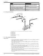
• An optional 4–inch long tube around the bolts at the top of the concrete allows some
flexibility in bolt alignment to match the holes in the baseplate.
• Allow enough bolt length for grout, shims, lower baseplate flange, nuts, and washers.
2
4
1
3
5
1. Foundation bolt
2. Pipe sleeve
3. Washer
4. Built-up concrete foundation
5. Optional 4–inch tube around the bolts
4.1.4 Level the base on a concrete foundation
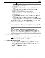
1. Place the pump on its concrete foundation.
2. Place 1.00 in./(25.40 mm) thick steel shims or wedges on both sides of each anchor
bolt in order to support the pump .
This also provides a means of leveling the base.
Add and remove shims under the base to level and plumb the pump shaft and flanges.
The baseplate does not have to be level.
4
1
5
2
3
6
7
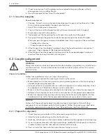
1. Locate the shims to allow removal after grouting.
2. Grout only to top of base rail
3. Pump base rail
4. Grout
5. Concrete foundation
6. 1” (25.40 mm) Gap
7. Allow 1” for shims. Place on both sides of anchor bolts.
3. Draw anchor bolts tight against the base and observe pump and motor shafts or
coupling hubs for alignment.
Temporarily remove the coupling guard for checking alignment.
4. If the alignment needs improvement, add shims or wedges at appropriate positions
under the base so that retightening of anchor nuts shifts shafts into closer alignment.
Repeat this procedure until a reasonable alignment is reached.
A reasonable alignment is that which is agreed upon by the pump contractor and the
accepting facility. Final alignment procedures are covered in “Alignment procedures.”
4 Installation
G&L Pumps Series A-C 8100 Base Mounted Centrifugal Pump INSTRUCTION MANUAL
15
Содержание G&L A-C 8100 Series
Страница 1: ...INSTRUCTION MANUAL AC5659D G L Pumps Series A C 8100 Base Mounted Centrifugal Pump...
Страница 2: ......


