Operation Manual
61
www.XMFG.com
Operation
9.
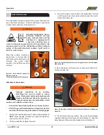
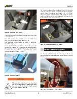
Connect the quick attach couplers (this only applies to at-
tachments with a quick attach hydraulic system).
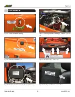
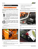
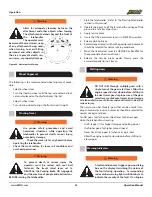
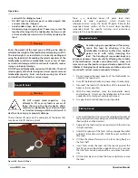
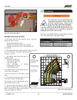
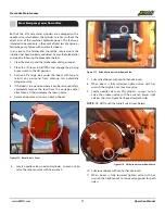
Figure 94. Manually Thread the Aux Hoses Through the Horse Head
When Connecting or Removing the Attachment
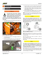
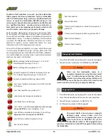
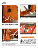
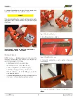
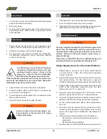
Figure 95. Quick Attach Couplers
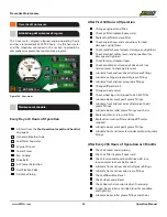
Figure 96. Quick Attach Lock Lever
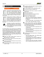
7.
Raise the quick attach lock lever.
Attachment Removal
NOTE:
To remove a standard carriage with forks, spread the
forks apart on the carriage shaft. This provides adequate sup-
port for the carriage to stand alone.
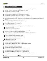
•
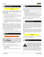
Bring the telehandler to a complete stop.
•
Move the travel select lever to NEUTRAL (N).
•
Set the parking brake switch to ON (engaged).
•
Extend the boom approximately 18 to 20 inches.
•
With the attachment 10”-12” off of the ground, tilt the
attachment backward.
•
Disconnect the quick attach couplers (this only applies to
attachments with a quick attach hydraulic system).
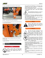
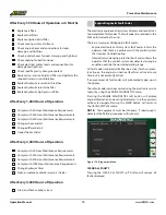
8.
Pull out the quick attach pin at the bottom of the quick
attach adapter.
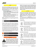
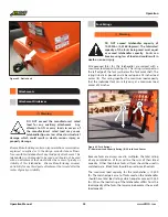
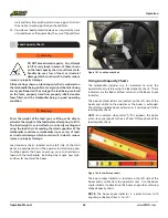
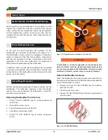
Figure 97. Pull Quick Attach Pin from Attachment and Quick Attach
Adapter.
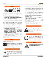
Caution
The hydraulic auxiliary hoses need to be threaded manually
through the horse head when connecting or removing the
attachment.

