XtendLan DPC-536 Скачать руководство пользователя страница 19

19

- - - - - - - -

P r e s

* B a c k

V i d e

8. USING DEBUG TOOLS

8.1.

How to enter debug tools menu

> > D E B U G S T A T E < <

- - - - - - - - - - - - - - - - - - - - - - - - - - -

# - # P r o g r a m G u i d e

0 - # R e d i a l L a s t N b r s

1 - # D o w n l o a d f r o m P C

2 - # D e b u g T o o l s

- - - - - - - - - O p t i o n s - - - - - - - - - -

< > V o l u m e A d j u s t

< > A u t o D i a l B a c k

< > D i s p l a y N e t D a t a

<

> D i s p l a y A l a r m

< > G u a r d U n i t O n l i n e

- - - - - - - - - - - - - - - - - - - - - - - - - - -

D e b u g M e s s a g e a r e a

> > D E B U G T O O L S < <

- - - - - - - - - - - - - - - - - - - - - - - - - - -

[ 1 ] < > V o l u m e A d j u s t

[ 2 ] < > A u t o D i a l B a c k

[ 3 ] < > D i s p l a y N e t

[ 4 ] < ● > D i s p l a y A l a r m
[ 5 ] O n l i n e S e a r c h i n g . . .

[ 6 ] M o n i t o r P r o p e r t y . . .

[ 7 ] V o l t a g e M e a s u r i n g . . .

[ 8 ] S i m u l a t e C a l l i n g . . .

- - - - - - - - - - - - - - - - - - -

s 1 ~ 8 t o s e l e c t

> > O n l i n e S e a r c h i n g < <

[ - - - - ] ~ [ - - - - ]

( S e a r c h R a n g e )

* B a c k

# R u n

V i d e o E n t r y S y s t e m

o E n t r y S y s t e m

V i d e o E n t r y S y s t e m

Make sure the Door Station runs

as Debug Mode, press “2”, “#”

When Debug Tools menu is shown:

Press 1~4 to reverse debug option;

Press 5~8 to launch debug command.

For example, press “5” in

last step will launch Online

searching menu

Note.

-

Each Debug Option can be activated or de-activated independently, and marked in screen if activated.

-

Each Debug Command is a sub-menu to execute and show result.

-

The “Guard Unit Online” item will be marked or cleared dynamically, according to Guard Unit state.

-

On Debug State menu, the 2 bottom lines are served as displaying events, logs and debug data.

8.2.

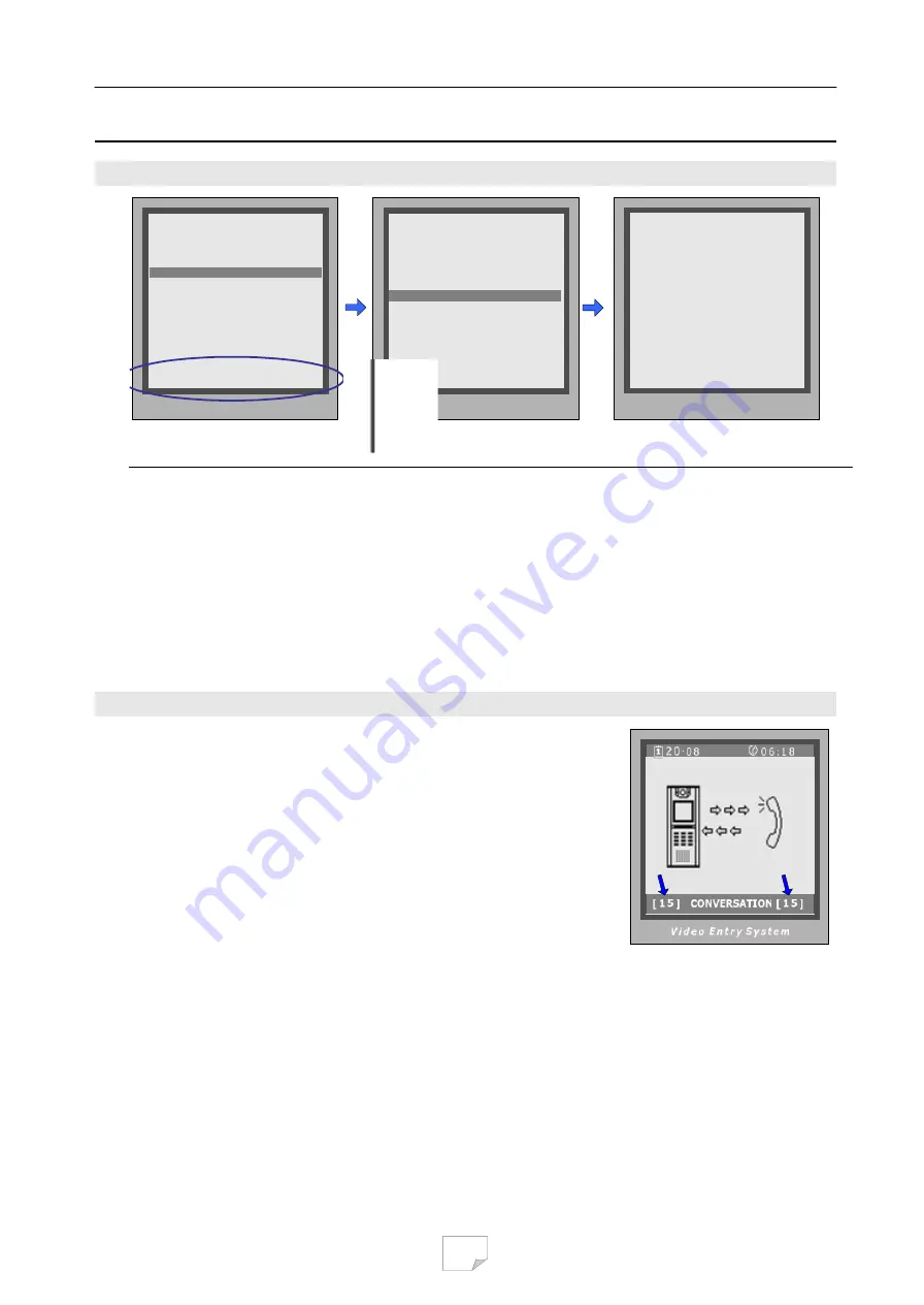
Debug Tools > Volume Adjust

Door Station has the advanced feature that conversation volume of

both directions can be adjusted in digital method.

After

Volume-Adjust

is activated, if Door Station calls a Monitor and

enters talking state, current volume values are shown on bottom line.

The left value means “

Door Station talks to Monitor

” channel, and

the right value means “

Monitor talks to Door Station

”. Each value

can be adjusted separately, ranges for 01 to 25, and 15 by default.

Use “1”/“4” key to increase/decrease the left value; and “3”/”6” for

the right value. The adjustment is saved automatically.

Important Notes:

-

For installations using handfree Monitors, it’s important that volume values in both directions must be

adjusted correctly. Otherwise, conversation maybe hard to hear, or discontinuously, or feedback.

-

The handfree conversation quality between Monitor and Door Station is related to distance between them.

On the back of handfree Monitor, a yellow rheostat (Variable Resistor) serves as adjuster, to adapt to

distance. If long distance cable is used or in interferential area for the Monitor, please adjust the rheostat

(VR) carefully to make the conversation in both directions clearly and continuously.

Содержание DPC-536

Страница 1: ...gram Monitor by means of Door Station 5 Door Station Programming 8 5 1 How to enter Program Menu 5 2 How to modify parameters 5 3 Program Menu overview 5 4 Basic Configuration Detail 6 Access Control...

Страница 2: ...ypad and screen on the Door Station panel However it is better to use the PC diagnose procedure when the Guard Unit is connected and works Please refer to the software manual Several system operation...

Страница 3: ...an be changed Program Code is located in PROGRAM 2 Unlock Code 8 Program Code see Chapter 5 4 Note that Administrator Code is also valid in all cases when Program Code is asked After the installation...

Страница 4: ...nversation volume in Door Station during talking state 3 2 How to activate Debug Mode in Door Station By means of keypad When Door Station is standby press key Input 9008 then input Admin Code 6666666...

Страница 5: ...de press the Monitor s CALL Button the Door Station LCM screen will show the Monitor s Room Code and Door Station will call back the Monitor automatically after 3 seconds if Auto Dial Back debug optio...

Страница 6: ...in both states Normal or Debug mode Please see as below When in normal mode When Door Station is standby press key Input 8003 then input Program Code 88888888 by default Monitor Program is launched Wh...

Страница 7: ...displayed after 2 4s normally Important Notes Please note when Door Station runs in Monitor Program state the rest functions of system are blocked temporarily Valid program timing is limited in 10 se...

Страница 8: ...s twice to enter PROGRAM MENU 5 2 How to modify the parameter In PROGRAM MENU screen press numbers key to activate the Program Sub Menu In Program Sub Menu press numbers key to enter parameter setting...

Страница 9: ...5 3 PROGRAM MENU Overview 9...

Страница 10: ...from 1 to 5 2 2 numbers 5 Intercom Video If set to 0 when Monitor is called by Guard Unit or other Monitors the monitor screen CRT TFT doesn t turn on If set to 1 the screen will always be turned on i...

Страница 11: ...To configure system audio video channel number If set to 0 single channel when F4 A or no distributor are installed If set to 1 four audio channels and F4Q distributor should be used If set to 2 four...

Страница 12: ...in If set to 1 press 9 under standby will launch Name list screen Set to 0 no Name list screen launch 0 No Name List 5 HMC To activate Home Message function if HMS is installed If set to 1 activating...

Страница 13: ...nd Unlock Code 2 together which controlled by Code Nbrs parameter see Chapter 6 4 for reference If 8 digits code mode is configured only one Unlock Code can be used Private Unlock Mode In this mode ea...

Страница 14: ...for Private Code Unlock mode 1111 2 Unlock Code 2 To change 2nd unlock code in Common Code Unlock mode 2222 3 Code Err Alert If set to 1 when wrong codes were input for 3 times within 1 minute warning...

Страница 15: ...A c c e s s S e c u r i t y 7 C a r d M a n a g e m e n t 8 S y s t e m M a i n t a i n 9 A d v a n c e d C o n f i g P r e s s 1 9 t o s e l e c t B a c k V i d e o E n t r y S y s t e m 4 C l o c k...

Страница 16: ...0 The ACS address is 3 digits format just like Net Address and ranges from 121 to 240 Automatically Don t modify it 4 Clock To configure date and time only available when the Door Station has Access s...

Страница 17: ...r d 0 1 0 1 0 1 0 1 P l e a s e i n p u t M C o d e S h o w t h e C a r d C a r d 1 5 9 7 7 1 3 1 U p d a t e d B a c k S a v e S a v e B a c k S a v e V i d e o E n t r y S y s t e m n t r y S y s t...

Страница 18: ...ew Master Card After this operation the previous Master Card is deleted automatically Please note that User Cards can t be converted into Master Card 7 3 3 Card information in Debug Mode When Door Sta...

Страница 19: ...result The Guard Unit Online item will be marked or cleared dynamically according to Guard Unit state On Debug State menu the 2 bottom lines are served as displaying events logs and debug data 8 2 Deb...

Страница 20: ...L a s t N b r s 1 D o w n l o a d f r o m P C 2 D e b u g T o o l s O p t i o n s V o l u m e A d j u s t A u t o D i a l B a c k D i s p l a y N e t D a t a D i s p l a y A l a r m G u a r d U n i t...

Страница 21: ...serial Monitors were designed without A D converter and don t support In Debug State press 2 to enter Debug Tools select 7 Input Monitor s Room Code in 4 digits and then press The two voltage values a...

Отзывы: