background image

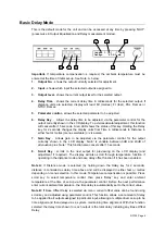
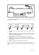
Press 'MENU' and select Delay Measurement using menu / scroll keys or parameter control.

Press 'ENTER' to load selection.

1.

Output No.

 - shows the output currently selected for use. All other outputs are muted in

this mode.

2.

Output Level

 - shows the current level in dB. for the selected output. This is adjustable

between -10 & -40dB but is set for -20dB when the measurement mode is first entered,
to reduce the risk of loudspeaker damage.

3.

Parameter Control

 - provides adjustment of output level for selected output.

4.

Scroll key

 - Allows the required output to be selected. (Once the measurement function

has been initiated, pressing this key toggles the tone burst frequency between 100Hz,
1kHz and 10kHz).

5.

Enter key 

- Pressing this key initiates the measurement function.

Note:

 To avoid instant acoustic feedback and possible loudspeaker damage, the

microphone must be disconnected from the DP100 input before quitting Delay Measurement

Mode.

DP100

Loudspeaker

Microphone

Mic-amp.

Input A

Output

Delay time (distance)

Power

Amp

Delay Measurement - Simplified Block Diagram

DP100 Page 13

3

2

5

1

4

=DELAY Measurement==
Output= 1    -20.0dB

Содержание DP100

Страница 1: ......

Страница 2: ...Functions 4 DP100 Block Diagrams 5 Operating The DP100 6 Preliminary Setup 7 Basic Delay Mode 8 Output Equalisation Mode 9 DP100 Equalisation Curves 10 Memory Store 11 Memory Recall 12 Delay Measurem...

Страница 3: ...g mains power This voltage is confirmed on the voltage label affixed to the rear of the unit The voltage selector switch is located inside the DP100 Refer adjustment to qualified personnel Do not expo...

Страница 4: ...e standard specification includes 80 memories MIDI for external control linking master slave units selectable operating level and security lock out function Delay measurement mode simplifies set up by...

Страница 5: ...In Output EQ mode the Delay key selects between the three EQ parameters Gain Frequency and Q 6 Gain Key Allows gain to be adjusted via the parameter control for the output currently shown in the LCD...

Страница 6: ...uts Separate 3 pin XLR connectors are provided for each audio input and output All terminations are fully balanced where pin 2 Hot pin 3 Cold and pin 1 Screen shield See page 17 for more information 6...

Страница 7: ...2 DELAY 3 BAND EQ GAIN D A OP LEV BAL OUT 3 DELAY 3 BAND EQ GAIN D A OP LEV BAL OUT 4 BAL IN B OP LEV METER A D B A S E D E L A Y Dual Configuration DELAY 3 BAND EQ GAIN D A OP LEV BAL OUT 1 BAL IN A...

Страница 8: ...type See page 11 for more information Memory Recall Allows recall of all currently used memories as selected via the parameter control See page 12 for more information Security System Allows a securit...

Страница 9: ...more information Preliminary Setup The following procedure should be followed when first installing the DP100 1 Select correct unit configuration via menu 2 Set maximum input level operating level vi...

Страница 10: ...y shown in the LCD display Gain is variable between 0dB and 40dB of attenuation plus mute This function also cancels after 15 seconds 8 Scroll Key scrolls to the next output for previewing on the LCD...

Страница 11: ...ut No shows the output currently selected for adjustment 2 Section No shows the parametric section currently selected 3 per output 3 Frequency displays centre frequency for the filter section currentl...

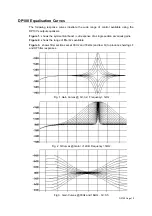
Страница 12: ...symmetrical boost cut response of a single section at various gains Figure 2 shows the range of filter Q s available Figure 3 shows filter sections set at 30Hz and 18kHz and low Q to produce shelving...

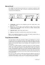
Страница 13: ...t required memory 4 Enter key Pressing this key stores all current parameters into the chosen memory Previously used memories identified by a after Mem No must be over written by pressing ENTER again...

Страница 14: ...shown on the DP100 s LCD display This system replaces the use of a tape measure or the trial and error approach allowing the required delay time to be determined quickly for each loudspeaker zone and...

Страница 15: ...adjustment of output level for selected output 4 Scroll key Allows the required output to be selected Once the measurement function has been initiated pressing this key toggles the tone burst frequen...

Страница 16: ...999 can be chosen via the parameter control 3 Parameter Control Allows the required security code number to be selected This number must be written down and saved for future use 4 Enter key Once the r...

Страница 17: ...en a memory is recalled The program change number is the same as the DP100 memory number being recalled i e 1 to 20 therefore if a Master DP100 is used to control a number of Slave DP100 units the cor...

Страница 18: ...2dB steps Centre frequency 20Hz 20kHz 1 24 octave steps Filter Q 0 5 to 32 Operating level Headroom selectable 3dB 8dB 15dB 20dB Temp Correction 0 C to 40 C in 1 steps Display 2 x 20 character backli...

Страница 19: ...g point for that option not a safe operating level Always ensure that this clipping point is no lower than that for the following equipment in the signal chain and allow extra margin if equalisation s...

Страница 20: ...to be defective provided that the product is returned shipping prepaid to an authorised XTA service facility Defects caused by unauthorised modifications misuse negligence act of God or accident or an...

Отзывы: