

5
Part Number
18143,
E, 01/28/2020
P
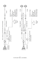
1BR
-S
01
-D
P
1CR
-S
01
-D
FS
-
X01 CA
BL
E XX’
FS
-T
01
R
ED
–
Po
w
er (+) 1.0
A
mp
F
u
se
fr
o
m Cir
cu
it Bre
ake
r
BL
A
CK
–
G
ro
u
n
d
(
-)
P
o
si
ti
ve
(
+)
vo
ltag
e
Fro
m
So
le
n
o
id
Cir
cu
it
Bre
ake
r (2A
)
(May b
e o
b
tai
n
e
d
@ Di
sp
lay U
n
it. 2A
fu
se
re
co
mmen
d
ed
)
So
le
n
o
id
V
alve
YE
LL
O
W
–
S
w
itch
in
g G
ro
u
n
d
2A
F
u
se
In
cl
u
d
e
d
FS
-
X01 CA
BL
E XX’
FS
-T
01
FS
-
X01 CA
BL
E XX’
FS
-T
01
P
2BS
-S
01
-D
R
ED
–
Po
w
er (+) 1.0
A
mp
F
u
se
fr
o
m Cir
cu
it Bre
ake
r
BL
A
CK
–
G
ro
u
n
d
(
-)
So
le
n
o
id
V
alve
YE
LL
O
W
–
S
w
itch
in
g G
ro
u
n
d
2A
F
u
se
In
clu
d
e
d
P
o
si
ti
ve
(
+)
vo
ltag
e
Fro
m
So
le
n
o
id
Ci
rc
u
it
Bre
ake
r (2A
)
(May b
e o
b
tai
n
e
d
@ Di
sp
lay U
n
it. 2A
fu
se
re
co
mmen
d
ed
)


