Xintex P-1BS-R Скачать руководство пользователя страница 8

Part Number


18143,


E, 01/28/2020 

Testing the Propane Fume Sensors 
 

WARNING 

DO NOT USE A PROPANE SOAKED RAG OR A PARTIALLY FULL CONTAINER OF PROPANE TO TEST A 
SENSOR.  THE RAW PROPANE COULD IGNITE, RESULTING IN SERIOUS INJURY.   
 
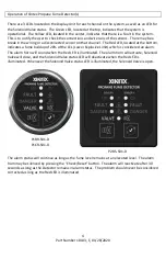
Test the Sensors by holding an unlit Butane lighter to the sensor.  Within a few seconds, the Red 

“Danger” LED should illu

minate and the alarm horn will sound.  Remove the lighter from the 

Sensor and mute the alarm horn.  After approximately one minute, the Red LED will shut off. 


Maintenance 
 
The system should be tested periodically in the fashion described in the previous sections.  Due to 
the harsh environmental conditions in marine applications, it is recommended to replace the 
Propane Fume Sensors every 3-4 years. 
 
In the Event of an Alarm 
 
Immediately have all passengers and crew exit the passenger compartment and vessel if possible.   
 
Ventilate the space being monitored. 
 
Carefully check all fuel lines and other potential sources of propane fume leaks.  If leaks are 
identified, shut off fuel supply and make any necessary repairs.   
 
 
Repairing Xintex Propane Fume Detection Components 
 
Xintex Propane Fume Detection Components are not field serviceable.  Components must be 
returned to the factory for any repairs. 
 
Returning Xintex Propane Detection Components 
 

No product may be returned for credit or repair without a written “Returned Material 
Authorization” (RMA) form.  Purchaser must call or email Fireboy

-Xintex 616-735-9380 or 

[email protected] for a RMA.  If due to extenuating circumstances a product is to be 
returned, after approval it must be received in 100% new/resalable condition.  Products stored by 
the buyer for more than 26 weeks may not be returned for any reason.  Maintaining fresh and 
current inventory is the responsibility of the buyer. 


Содержание P-1BS-R

Страница 1: ...ol 24V Solenoid P 1CS R Chrome Round Solenoid Control 12V Solenoid P 1CS 24 R Chrome Round Solenoid Control 24V Solenoid Dual Channel System P 2BS R Black Square Solenoid Control 12V Solenoid P 2BS 24...

Страница 2: ...talling the Display Unit P1BR S01 D P1CR S01 D P2BS S01D 6 Installing the Solenoid Valve for LPG Applications 6 Routing Sensor Cable s FS X01 CABLE XX 6 Installing Propane Fume Sensor s FS T01 7 Elect...

Страница 3: ...e system Specification System Specifications P 1BS R P 1CS R Operating Voltage 9 18V DC Nominal Current Draw 55mA 12V DC Maximum Current Draw 725mA 9V DC Operating Temperature 40 F 40 C to 185 F 85 C...

Страница 4: ...e bottom indicates a fume buildup of 20 of the LEL Lower Explosive Limit which is considered an alarm The alarm horn will sound when the Red LED is illuminated The alarm horn will actuate Solenoid Val...

Страница 5: ...er 2A May be obtained Display Unit 2A fuse recommended Solenoid Valve YELLOW Switching Ground 2A Fuse Included FS X01 CABLE XX FS T01 FS X01 CABLE XX FS T01 P2BS S01 D RED Power 1 0 Amp Fuse from Circ...

Страница 6: ...ctical The tank itself should be mounted outside the cabin or crew quarters to avoid the possibility of gas accumulation due to a leak NOTE TIGHTEN TO 12 13 FT LBS DO NOT OVER TIGHTEN NOTE ALL PIPING...

Страница 7: ...used Yellow 16 GA wire is provided for connecting the Display Unit to the Solenoid Valve Connect the Yellow wire to the Solenoid Valve Connect the positive voltage to the Solenoid Valve NOTE UNITS MAN...

Страница 8: ...ngers and crew exit the passenger compartment and vessel if possible Ventilate the space being monitored Carefully check all fuel lines and other potential sources of propane fume leaks If leaks are i...

Страница 9: ...ent of Fireboy Xintex LLC does not assume the costs of removal and or installation of the product or any other incidental costs of removal and or installation of the product or any other incidental co...

Отзывы: