4. System Networking
5.
For this access control operator panel, putting place 8 of the DIP switch to the
ON
position is equivalent to parallel connection of one 120ohm resistance
between the 485+ and 485- lines.
As shown in the figure below, put number 8 of the DIP switches of the first and last
control panels to
ON
position.
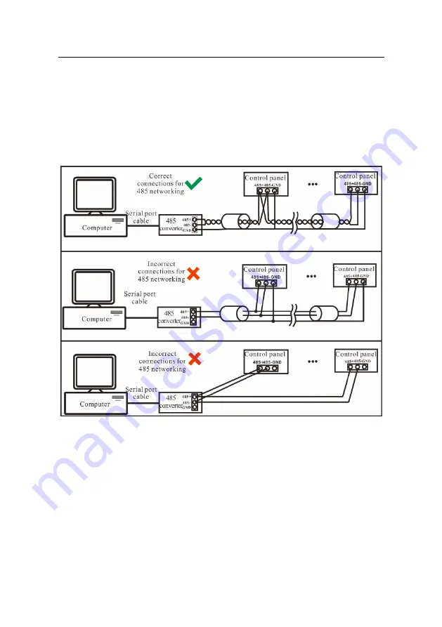
RS485 Communication System Networking
4.4 DIP Switch Settings
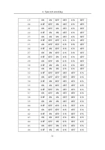
1. 485 address setting
Number 1-6 of the DIP switch are reserved to set device number for RS485
communication. The code is binary, and the lower places are in the front. When the
switch is set to ON position, it indicates 1 (on); when the switch is set downwards, it
indicates 0 (off).
29
Содержание C3-X60 Series
Страница 2: ......
Страница 4: ......
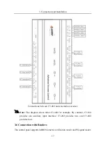
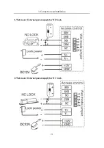
Страница 17: ...3 Connection and Installation C3 260 terminal connection diagram 13...
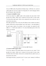
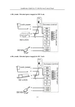
Страница 18: ...Installation Guide for C3 X60 Series Control Panel C3 460 terminal connection diagram 14...
Страница 37: ...4 System Networking 33...


