


PREPARING THE BINDER 120 FOR ON-LINE AND OFF-LINE OPERATION
XEROX DOCUMENT BINDER 120 OPERATOR MANUAL
3-3
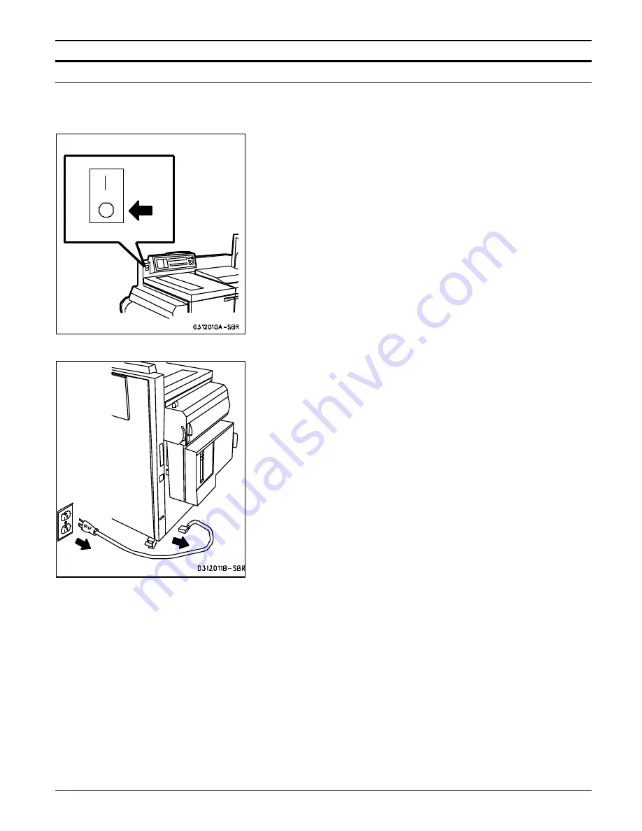
Connecting to a Xerox 5100
Use this procedure to connect the Binder 120 from the stand-alone
mode to a Xerox 5100 host machine.
1.
Press the Binder 120 Power Switch to the Off (
O
) position.
2.
Unplug the Binder 120 Power Cord from the electrical wall outlet
and the Binder 120.
•
Set the Power Cord on top of the Binder 120.
Содержание Document Binder 120
Страница 1: ...XEROX Xerox Document Binder 120 Operator Manual January 1999 701P99911 ...
Страница 20: ...TECHNICAL DATA 8 8 XEROX DOCUMENT BINDER 120 OPERATOR MANUAL Notes ...
Страница 38: ...PROBLEM SOLVING XEROX DOCUMENT BINDER 120 OPERATOR MANUAL 7 19 Notes ...
Страница 39: ...PROBLEM SOLVING 7 20 XEROX DOCUMENT BINDER 120 OPERATOR MANUAL Notes ...
Страница 42: ...CARE 6 4 XEROX DOCUMENT BINDER 120 OPERATOR MANUAL Notes ...
Страница 48: ...CUSTOMIZING YOUR BINDER 120 XEROX DOCUMENT BINDER 120 OPERATOR MANUAL 5 7 Notes ...
Страница 49: ...CUSTOMIZING YOUR BINDER 120 5 8 XEROX DOCUMENT BINDER 120 OPERATOR MANUAL Notes ...
Страница 64: ...MAKING THE BOOKS 4 16 XEROX DOCUMENT BINDER 120 OPERATOR MANUAL Notes ...
Страница 114: ...PREPARING THE BINDER 120 FOR ON LINE AND OFF LINE OPERATION 3 46 XEROX DOCUMENT BINDER 120 OPERATOR MANUAL Notes ...
Страница 125: ...GETTING TO KNOW THE BINDER 120 2 12 XEROX DOCUMENT BINDER 120 OPERATOR MANUAL Notes ...
Страница 133: ...INTRODUCTION XEROX DOCUMENT BINDER 120 OPERATOR MANUAL 1 9 Notes ...
Страница 134: ...INTRODUCTION 1 10 XEROX DOCUMENT BINDER 120 OPERATOR MANUAL Notes ...
Страница 137: ...TABLE OF CONTENTS viii XEROX DOCUMENT BINDER 120 OPERATOR MANUAL ...
Страница 138: ...NOTICES iv XEROX DOCUMENT BINDER 120 OPERATOR MANUAL ...


