background image

WorkCentre 3210/3220 Multifunction Printer Service Manual

2-3

Theory of Operation

Paper Path

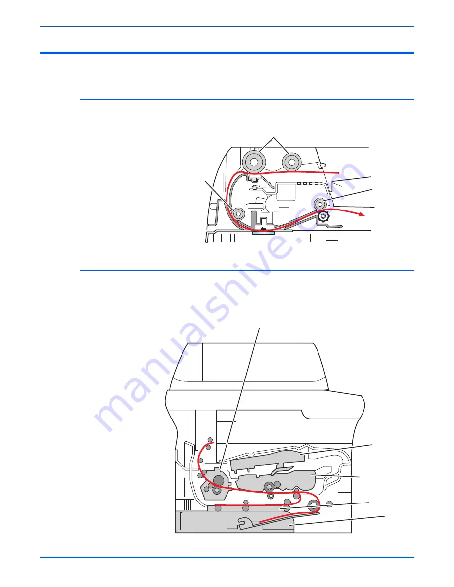
The following describes how media is transported through the printer.

ADF

Media is transported through the ADF by these components.

Printer

The media supplied from the Tray 1, or Tray 2, is transported through the 
printer as shown in the illustrations below. Media fed from the manual feed 
slot enters the media path at the registration roller.

ADF Feede

r

 A

ss

embly

ADF Feed Rolle

r

Pi

n

ch Rolle

r

s

3210mfp-113

La

s

e

r

 U

n

it

P

r

i

n

t Ca

r

t

r

idge

F

us

e

r

D

u

plex U

n

it

T

r

ay 2

s

3210mfp-112

Содержание 3210 - workcentre b/w laser

Страница 1: ...WorkCentre 3210 3220 Multifunction Printer WorkCentre 3210 3220 Service Manual ...

Страница 2: ......

Страница 3: ...ter Warning The following servicing instructions are for use by qualified service personnel only To avoid personal injury do not perform any servicing other than that contained in the operating instructions unless you are qualified to do so First Printing March 2009 ...

Страница 4: ...written consent from Xerox Corporation XEROX CentreWare WorkCentre PrintingScout and Walk Up are trademarks of Xerox Corporation in the United States and or other countries Adobe and PostScript are trademarks of Adobe Systems Incorporated in the United States and or other countries Apple Bonjour ColorSync EtherTalk Macintosh and Mac OS are trademarks of Apple Computer Inc in the United States and ...

Страница 5: ...ently accomplish a task A note can provide additional information related to a specific subject or add a comment on the results achieved through a previous action Caution A caution indicates an operating or maintenance procedure practice or condition that if not strictly observed results in damage to or destruction of equipment Warning A warning indicates an operating or maintenance procedure prac...

Страница 6: ...t surface on or in the printer Use caution to avoid personal injury Warning Use caution to avoid personal injury Use caution or draws attention to a particular component Refer to the manual s for information Do not touch the OPC Drum Do not expose the item to sunlight Do not tilt the Print Cartridge Do not expose item to high temperature Recycle the item 35 C 95 F 0 C 32 F ...

Страница 7: ... install a properly grounded outlet If the product loses its ground connection contact with conductive parts may cause an electrical shock A protective ground connection by way of the grounding conductor in the power cord is essential for safe operation Disconnecting Power Warning Turning the power Off using the power switch does not completely de energize the printer Disconnect the power cord fro...

Страница 8: ...rap before applying power to the unit under test to avoid potential shock After removing a static sensitive assembly from its anti static bag place it on a grounded conductive surface If the anti static bag is conductive you may ground the bag and use it as a conductive surface Do not use freon propelled chemicals These can generate electrical charges sufficient to damage some devices Do not remov...

Страница 9: ... a well ventilated area Warning Labels Read and obey all posted warning labels Throughout the printer warning labels are displayed on potentially dangerous components As you service the printer check to make certain that all warning labels remain in place Safety Interlocks Make sure all covers are in place and all Interlock switches are functioning correctly after you have completed a printer serv...

Страница 10: ...recyclable Under various state and local laws it may be illegal to dispose of the cartridge into the municipal waste Check with the local waste officials for details on recycling options or the proper disposal procedures Fuses Warning Do not install a fuse of a different type or rating Installing the wrong type or rating of fuse can cause overheating and a risk of fire Part Replacement Only use ge...

Страница 11: ...ent unless you are instructed to do so by a service procedure Servicing Mechanical Components When servicing mechanical components within the printer manually rotate the drive assemblies rollers and gears Warning Do not try to manually rotate or manually stop the drive assemblies while any printer motor is running Servicing Fuser Components Warning This printer uses heat to fuse the toner image to...

Страница 12: ...inter separately from Tray 2 When shipping the printer repack the printer using the original packing material and boxes or a Xerox packaging kit Instructions for repacking the printer are included in the kit If you do not have all the original packaging or are unable to repackage the printer contact your local Xerox service representative Caution Failure to properly repackage the printer for shipm...

Страница 13: ...ns However there is no guarantee that interference will not occur in a particular installation If this equipment does cause harmful interference to radio or television reception which can be determined by turning the equipment Off and On the user is encouraged to try to correct the interference by one or more of the following measures Reorient or relocate the receiver device being interfered with ...

Страница 14: ... 2004 108 EC as amended Approximation of the laws of the member states related to electromagnetic compatibility Certificates of Indebtedness National Bank Currency Coupons from Bonds Federal Reserve Bank Notes Silver Certificates Gold Certificates United States Bonds Treasure Notes Federal Reserve Notes Fractional Notes Certificates of Deposit Paper Money Bonds and Obligations of certain agencies ...

Страница 15: ...cates may be photocopied 10 Badges Identification Cards Passes or Insignia carried by military personnel or by members of the various Federal Departments such as FBI Treasure etc Unless photograph is ordered by the head of such department or bureau Reproducing the following is also prohibited in certain states Automobile Licenses Driver s Licenses Automobile Certificates of Title The above list is...

Страница 16: ...es of fine or imprisonment may be imposed on those found guilty of making such reproductions Currency notes Bank notes and cheques Bank and government bonds and securities Passports and identification cards Copyright material or trademarks without the consent of the owner Postage stamps and other negotiable instruments This list is not inclusive and no liability is assumed for either its completen...

Страница 17: ... REN without a decimal point e g 03 is a REN of 0 3 For earlier products the REN is separately shown on the label To order the correct service from the local telephone company please provide the Facility Interface Code FIC and Service Order Code SOC listed below FIC 02LS2 SOC 9 0F You may also have to provide the USOC Jack code and the Ringer Equivalence Number REN If this Xerox equipment causes h...

Страница 18: ...ake sure their own protection that the electrical ground connections of the power utility telephone lines and internal metallic water pipe systems if present are connected together This precaution may be particularly important in rural areas Caution User should not attempt to make such connections themselves but should contact the appropriate electric inspection authority or electrician as appropr...

Страница 19: ... another item of Telepermitted equipment of a different make or model nor does it imply that any product is compatible with all of Telecom s network services The equipment may not be capable of correct operation at the higher data speeds designated 33 6 kbps and 56 kbps connections are likely to be restricted to lower bit rates when connected to some PSTN implementations Telecom will accept no res...

Страница 20: ...attempts to the same number within any 30 minute period for any single manual call initiation and The equipment shall go on hook for a period of not less than 30 seconds between the end of one attempt and the beginning of the next attempt For automatic calls to different numbers The equipment shall be set to ensure that automatic calls to different numbers are spaced such that there is no less tha...

Страница 21: ...hooting procedures for error messages displayed by the printer Chapter 4 General Troubleshooting This section describes the operation of Tech mode and Embedded Diagnostic Control EDC diagnostic utilities In addition this section includes troubleshooting methods for situations where error indicator is not available Chapter 5 Print Quality Troubleshooting This section focuses on techniques to correc...

Страница 22: ...xx WorkCentre 3210 3220 Multifunction Printer Service Manual ...

Страница 23: ... 9 Additional RAM 1 9 Optional Tray Assembly 1 9 Maintenance Items 1 10 Consumables 1 11 Specifications 1 12 Printer Specifications 1 12 Print Speed 1 13 First Print Output Time 1 13 Memory Specifications 1 13 Scanning Specifications 1 14 Copy Specifications 1 15 First Copy Output Time 1 15 Fax Specifications 1 16 Environmental Specifications 1 17 Electrical Specifications 1 17 Warm Up Time 1 18 I...

Страница 24: ...x 2 29 Engine F W 2 32 3 Error Messages and Codes Introduction 3 2 Error Information Report 3 2 Servicing Instructions 3 3 Measurement Techniques 3 4 Error Messages and Procedures 3 5 Error Message Abbreviations 3 5 Error Message Summary 3 6 Jam Errors 3 8 Paper Jam 0 3 9 Paper Jam 1 3 10 Paper Jam 2 3 12 Document Jam 3 13 Duplex Jam 3 15 Tray and Media Errors 3 16 Paper Empty 3 16 Paper Mismatch ...

Страница 25: ...ication for Front Cover 4 13 Paper Rolled in the Fuser 4 14 Fuser Gear Damaged from Overheating 4 15 Paper Rolled on the OPC Drum 4 16 Multi Sheet Picks 4 17 Inoperable Printer Troubleshooting 4 18 The Printer is Not Responding to the Print Command 4 18 The Printer is Not Responding to a Print Command due to Incorrect Setup 4 18 Scanner Malfunction 4 19 ADF Does Not Feed Media 4 19 Fax Troubleshoo...

Страница 26: ... 5 16 Ghosting 3 5 17 Vertical White Line 5 18 Vertical Lines are Curved 5 19 Vertical Black Line or Band 5 20 Horizontal Black Line and Band 5 21 Black White Spot 5 22 Skew 5 23 Stains on the Front of the Page 5 25 Stains on the Back of the Page 5 26 Blank Page 1 5 27 Blank Page 2 5 28 Incomplete Fusing 5 29 Incorrect Magnification 5 30 Lines or Streaks from ADF 5 31 Spots from ADF 5 32 Media Dam...

Страница 27: ...arts Disassembly Overview 8 2 Standard Orientation of the Printer 8 2 Preparation 8 3 Notations in the Disassembly Text 8 4 Fastener Types 8 5 Maintenance Items and Consumables 8 6 Transfer Roller 8 6 Print Cartridge 8 8 Pick Up Roll 8 9 Tray Feed Pad Assembly 8 11 Fuser 8 13 Thermistor 8 15 Thermostat 8 16 Heat Roller 8 17 Large Pressure Roller 8 21 Small Pressure Roller 8 24 Halogen Lamp 8 27 Au...

Страница 28: ... Roller 8 73 Pick Up Gear 8 76 Exit Idle Gear 8 77 Feed Gear 8 78 Pick Up Solenoid 8 79 Upper Exit Frame 8 80 Exit Roller 8 81 Feed Actuator 8 82 Duplex Actuator 8 84 Feed Sensor 8 86 Paper Empty Sensor 8 88 Feed Roller 8 90 Empty Actuator 8 91 Exit Actuator 8 92 Exit Sensor 8 93 Xerographics 8 95 Laser Unit 8 95 CRUM Terminal 8 96 Exit Guide 8 97 Rear Guide Unit 8 97 Drive 8 98 Drive Unit Assembl...

Страница 29: ...over 9 22 Parts List 6 3 Platen Assembly 9 24 Parts List 6 4 UI Assembly 9 26 Parts List 7 0 Cassette Assembly 9 28 Parts List 8 0 Fuser 9 30 Parts List 9 0 Duplex Unit 9 32 Options 9 34 Parts List 10 0 Optional Feeder Assembly 9 34 Xerox Supplies and Accessories 9 37 10 Wiring Component Locator Diagrams 10 2 Component Locator 10 2 Map 1 Circuit Board Locator 10 3 Map 2 Drive Locator 10 4 Map 3 Se...

Страница 30: ...xxviii WorkCentre 3210 3220 Multifunction Printer Service Manual Reference WorkCentre 3210 3220 Menu Map A 2 Tech Mode Menu Map A 3 Acronyms and Abbreviations A 4 Index ...

Страница 31: ...on In this chapter Printer Introduction and Overview Printer Configurations Parts of the Printer Printer Options Maintenance Items Consumables Specifications Print Cartridge Life Diagnostics CentreWare IS Power Save Mode Reports ...

Страница 32: ...ory media capacity and functionality Memory upgrades are available to increase from 128 MB standard RAM up to 384 MB maximum An Optional Tray Assembly adds 250 sheets of input storage Technical Support Information The Xerox WorkCentre 3210 3220 Multifunction Printer Service Manual is the primary document used for repairing maintaining and troubleshooting the printer To ensure complete understandin...

Страница 33: ... 3 No Standard SPL No Standard Interface USB 2 0 Hi Speed Standard Standard Ethernet Interface 10 100 Base TX 10 100 Base TX Network Protocols IPv4 IPP Secure IPP HTTP Port9100 LPD DDNS mDNS Bounjour SLP DHCP Auto IP WINS SNMPv3 SSDP SMTP IPP Secure IPP HTTP Port9100 LPD DDNS mDNS Bounjour SLP DHCP Auto IP WINS SNMPv3 SSDP Network Protocols IPv6 DHCPv6 HTTP Port9100 LPD IIP Secure IIP MLDv2 ICMPv6...

Страница 34: ... Guides 9 Front Cover 2 ADF Input Tray 10 Output Support 3 ADF Output Tray 11 Control Panel 4 USB Port 12 ADF Cover 5 Paper Level Indicator 13 Print Cartridge 6 Optional Tray Assembly 14 Manual Feeder with Guides 7 Tray 1 15 Scanner Lid 8 Manual Tray 16 Document Glass 1 2 3 4 5 6 7 8 9 10 11 12 15 16 s3210mfp 081 13 14 ...

Страница 35: ...anual 1 5 General Information Rear View 1 Telephone Line Connector 6 DIMM Cover 2 Extension Connector 7 Handle 3 Power Switch 8 15 pin Optional Tray Connection 4 Power Receptacle 9 Ethernet Port 5 Rear Cover 10 USB Port 1 2 3 4 5 6 7 8 9 10 s3210mfp 082 ...

Страница 36: ...orts Ethernet networks LED State Printer State Active LED Random Blink Normal NPC Normal packet receive Active LED Regular Blink Normal NPC No Packet Active LED Off On Maintenance NPC Initial Error Link LED On Link LED On Normally linked Link LED Off Link LED Off Link Error RJ 45 Jack Link LED Green Active LED Orange s3210mfp 148 ...

Страница 37: ...enus 9 Left Right Arrow Scroll through the options available in the selected menu and increase or decrease values 10 OK Confirms the selection on the screen 11 Back Returns to the upper menu level 12 Number Keypad Dials a number or enters alphanumeric characters 13 Address Book Allows the user to store frequently used fax numbers in memory or search for stored fax numbers or email addresses 14 Red...

Страница 38: ... System Setup Contains printer setup functionality Network Contains network setup functionality LED State Printer State Green The printer is powered on and can be used Flashing Green When the green LED slowly blinks the printer is receiving data from the computer When the green LED rapidly blinks the printer is printing data Red The Print Cartridge is empty or needs to be replaced A problem has oc...

Страница 39: ...nter features one memory slot that supports an additional 256 MB for a maximum of 384 MB Memory modules must meet the following characteristics 200 Pin DDR2 DIMM 8 chip type Unbuffered Non parity The printer s Configuration page lists the amount of installed RAM Optional Tray Assembly The Optional Tray increases the input capacity by 250 sheets and attaches underneath Tray 1 using a single connect...

Страница 40: ...on typical office printing with 5 coverage on 24 lb paper Print life is not guaranteed and varies depending on usage habits WorkCentre 3210 3220 Maintenance Items Item Print Life Fuser 50 000 pages Pick Up Roll 50 000 pages Transfer Roller 50 000 pages Tray Feed Pad 50 000 pages ADF Feeder Assy 50 000 pages ADF Rubber Feed Pad 20 000 pages Customer replaceable Fuser ADF Feeder Assembly ADF Rubber ...

Страница 41: ...rint Cartridge is the only consumable The Print Cartridge CRUM Customer Replaceable Unit Meter records toner usage data When the toner count nears empty Life End status is displayed to indicate toner empty Print Cartridge Print Life Standard Capacity 2 000 pages High Capacity 4 000 pages s3210mfp 003 ...

Страница 42: ...rm Up Time Power On UI Ready 54 sec 54 sec Power On first page print Less than 17 sec Less than 17 sec Power Save UI ready 2 sec 2 sec Power Save first print Less than 17 sec Less than 17 sec Power Save Settings 1 120 minutes 1 120 minutes Printer Life 100 000 pages or 5 years 100 000 pages or 5 years Average Monthly Print Volume average 800 PV month 800 PV month Maximum Duty Cycle 30 000 pages mo...

Страница 43: ...ntil a single page is printed and delivered to the output tray Memory Specifications Media WorkCentre 3210 ppm WorkCentre 3220 ppm Letter 24 30 A4 24 28 Legal 20 24 Duplex Letter N A 15 A4 N A 14 Legal N A 12 Model FPOT sec WorkCentre 3210 Less than 9 5 sec WorkCentre 3220 Less than 8 5 sec Characteristic Specifications Minimum 128 MB on board Maximum 384 MB Supported RAM Supports up to 384 MB of ...

Страница 44: ...Up to 4800 x 4800 dpi Up to 4800 x 4800 dpi Scan to USB 100 200 300 dpi 100 200 300 dpi Scan to Application 75 150 200 300 600 dpi 75 150 200 300 600 dpi Scan to Email N A N A Maximum Scanning Area Width Max Document 216 mm 8 5 in Effective Scan Width 208 mm 8 2 in Length Document Glass 297 mm 117 in ADF 348 mm 13 7 in Scan Interface TWAIN WIA TWAIN WIA File Formats JPG TIFF BMP PDF JPG TIFF BMP P...

Страница 45: ...9 Collation Yes ADF only Yes ADF only Duplex Copy No Manual Manual Duplex Yes Automatic Standard Automatic Background Suppression Standard Standard ID Card Copy Standard Standard Darkness Control Standard Standard Photo Mode Standard Standard Cloning Document Glass Only Document Glass Only Poster Document Glass Only Document Glass Only Copy Resolution dpi Text 600 x 600 600 x 600 Text Photo 600 x ...

Страница 46: ...x 98 dpi Fine Up to 203 x 196 dpi Super Fine Up to 300 X 300 of Auto Redial Attempts Up to 13 attempts Broadcast Group Dialing Number Up to 200 Speed Dialing Number 209 locations Max Phone Stored 200 Fax Forward to Fax Standard Auto Reduction Standard Last Number Redial Standard PC Fax send only Standard Secure Fax Standard Distinctive Ring Standard Send Confirmation Standard Auto Dial List Report...

Страница 47: ...s 8 200 feet Acoustic Noise Level Printing Less than 49 0 dBA Standby Less than 26 0 dBA Copying Less than 53 0 dBA Characteristic Specifications Power Supply Voltage Frequency Line Voltages 100 127 VAC 10 6 220 240 VAC 10 6 Frequency Range 50 60 Hz 3 Hz Current Capacity 110 V 9 0A 220 V 4 5A Power Consumption AC 110 V AC 220 V Standby Less than 60 W Less than 60 W Sleep Mode Less than 12 W Less t...

Страница 48: ...ed Print Quality Area Paper Width A B A Left Margin 4 23 mm B Right Margin 4 23 mm Paper Length C D C Top Margin 4 23 mm D Bottom Margin 4 23 mm Maximum 3 mm from edge of paper Characteristic Specifications Skew Vertical 2 0 mm Tray 1 241 3 mm Based on 0 0082 mm mm 2 5 mm Duplex SCF 241 3 mm Based on 0 0103 mm mm 3 5 mm ADF 241 3 mm Based on 0 0103 mm mm Horizontal 1 5 mm Tray 1 2 0 mm 177 8 mm Ba...

Страница 49: ...m 16 6 in Width 444 5 mm 17 5 in 444 5 mm 17 5 in Depth 393 7 mm 15 5 in 393 7 mm 15 5 in Weight base printer with standard fill print cartridge 17 8 kg 39 0 lb 17 8 kg 39 0 lb Optional Tray Assembly Height 91 4 mm 3 6 in 91 4 mm 3 6 in Width 363 0 mm 14 3 in 363 0 mm 14 3 in Depth 401 3 mm 15 8 in 401 3 mm 15 8 in Weight 2 6 kg 5 7 lb 2 6 kg 5 7 lb 71 2 cm 28 in 10 cm 3 9 in 10 cm 3 9 in 48 3 cm ...

Страница 50: ...order to function properly the printer must be placed on a surface with the following minimum dimensions 2 Mounting surface flatness must be within the specified range The printer must not be tipped or tilted more than 2 mm 0 08 inch Failure to adhere to the specified mounting specifications will void all guarantees of print quality and or performance 2 mm 0 08 in 2 mm 0 08 in s3210mfp 083 ...

Страница 51: ... 69 in 210 x 297 mm Yes Yes Yes A5 5 82 x 8 26 in 148 x 210 mm Yes Yes No B5 ISO 6 93 x 9 84 in 176 x 250 mm Yes Yes No B5 JIS 7 18 x 10 12 in 182 x 257 mm Yes Yes No Custom Page Size Yes Yes No Transparency Letter A4 Refer to Plain Paper Yes Yes Yes Labels Letter Legal Folio Oficio A4 JIS B5 ISO B5 Executive A5 A6 Refer to Plain Paper Yes No No Card Stock Letter Legal Folio Oficio A4 JIS B5 ISO B...

Страница 52: ... Premium Transparency Yes No No Envelope 75 90g m2 20 24 lb Yes No No Custom 60 163 g m2 16 43 lb Yes No No Supported Envelopes Type Dimension Manual Feeder Tray 1 2 Duplex 10 Commercial Envelope 4 12 x 9 5 in 105 x 241 mm Yes No No Monarch Envelope 3 88 x 7 5 in 98 4 x 190 5 mm Yes No No B5 Envelope 6 93 x 9 84 in 176 x 250 mm Yes No No C5 Envelope 6 38 x 9 02 in 162 x 229 mm Yes No No C6 Envelop...

Страница 53: ...he printer performs several self tests When turned On a routine of power up tests POST check key operational characteristics During operation the printer monitors system performance 2 Manual Diagnostics EDC Tech mode and test prints are all tools for the diagnosis and repair of printer problems These tools are only availabe to qualified service personnel CentreWare IS The CentreWare IS enables the...

Страница 54: ...rts The following reports are available in the WorkCentre 3210 3220 printer The reports can be printed using the printer s Control Menu or CentreWare IS Configuration Report Two types of Configuration report are available Printer Configuration report and Network Configuration report Report Print Method Control Panel CentreWare IS Network Printer Configuration Page Yes Yes Network Configuration Pag...

Страница 55: ...able in Tech mode and lists a percentage of remaining toner print and scan page counts and Print Cartridge capacity Page Count Page Count information is listed on the Configuration Report Clean Drum Page The Print Cleaning page is printed when a Cleaning procedure is performed Refer to Cleaning the Print Cartridge on page 7 3 for detailed information ...

Страница 56: ...1 26 WorkCentre 3210 3220 Multifunction Printer Service Manual General Information ...

Страница 57: ...2 Chapter Theory of Operation In this chapter Operational Overview Paper Path Image Input Terminal Image Output Terminal ...

Страница 58: ...r image System Overview The WorkCentre 3210 3220 Multifunction Printer is divided into two main components the Image Input Terminal IIT ADF and Scanner and the Image Output Terminal IOT Print Engine The WorkCentre 3210 3220 Multifunction Printer consists of the Automatic Document Feeder ADF Assembly Scanner Assembly Control Panel Print Engine Duplex Unit 3220 only and Optional Tray Assembly s3210m...

Страница 59: ...nsported through the ADF by these components Printer The media supplied from the Tray 1 or Tray 2 is transported through the printer as shown in the illustrations below Media fed from the manual feed slot enters the media path at the registration roller ADF Feeder Assembly ADF Feed Roller Pinch Roller s3210mfp 113 Laser Unit Print Cartridge Fuser Duplex Unit Tray 2 s3210mfp 112 ...

Страница 60: ... Unit and Tray Feed Pad The rollers and sensors in the paper feed path control paper registration and guide the paper through the image transfer image development image fusing and exit assemblies The paper path has an anti static connection to ground to eliminate problems due to static charge on the paper Pick Up Roll Tray 2 Duplex Unit Tray 1 Manual Feeder Feed Roller Tray Feed Pad s3210mfp 244 ...

Страница 61: ...ry of Operation Manual Feeder The manual feeder is used to hold non standard or custom paper sizes and special media envelopes transparencies etc The manual feeder uses a friction pad method to ensure paper is separated and can only hold 1 sheet of paper s3210mfp 128 ...

Страница 62: ...which can be adjusted for various paper sizes A paper level indicator located in front of the Tray indicates the amount of remaining paper Optional Tray Assembly The Optional Tray Assembly Tray 2 add a second 250 sheet input tray Tray 2 has a separate feed mechanism Holder Pad Paper Guide Paper Guide Rear Paper Guide Knock Up P Plate s3210mfp 014 s3210mfp 002 ...

Страница 63: ...Roller is used to pick up and feed paper into the printer and remove static charge on the paper Feed Roller Registration The Feed Roller arranges paper transfers paper detects paper and removes jam Feed Roller top area of the printer Feed Roller bottom area of the printer s3210mfp 013 s3210mfp 010 s3210mfp 080 ...

Страница 64: ...en paper feeds into the printer it passes over the Feed Pad Assembly that uses a spring loaded friction pad to separate the sheets of paper Duplex Unit The Duplex Unit available on the WorkCentre 3220 only uses a side feeding method When a jam occurs in the front or rear part of the printer the Duplex Unit can be removed to access the jam area Duplex Unit s3210mfp 129 ...

Страница 65: ...inal IIT generates the image data for copies and scans and is made up of two major subsystems Automatic Document Feeder ADF Scanner Assembly with the Control Panel Automatic Document Feeder The ADF automatically feeds original documents from the ADF input tray ADF Assembly ADF Hinges Control Panel ADF Connector s3210mfp 130 ...

Страница 66: ... 3210 3220 Multifunction Printer Service Manual Theory of Operation ADF Feeder Feed Pad and Sensors s3210mfp 237 ADF Rubber Feed Pad ADF Feeder Assembly 2 ADF Exit Sensor Registration Sensor Empty Sensor s3210mfp 245 ...

Страница 67: ...Feeder is designed to work with the ADF Rubber Feed Pad to ensure that only one sheet of paper is fed at a time ADF Motor The ADF motor drives the pick and feed roller ADF Connector An electrical connector on the rear of the ADF connects to a receptacle on the rear of the flatbed portion of the IIT The ADF connector communicates with the scanner board and that communication is passed to the IOT AD...

Страница 68: ...canning original documents and images Contact Image Sensor Scans the original converting the image in data CVT Window This portion of the document glass is a part of the ADF paper path The function of this window is to allow the scan head to image an original being fed through the ADF Control Panel The Control Panel is the user interface with the printer s3210mfp 132 CVT Window Control Panel Docum...

Страница 69: ... to the paper Drive Unit Assembly The Drive Unit Assembly receives power from the Main Controller Board The Main Motor provides drive energy to the paper feed Print Cartridge Fuser Pick Up Roller Feed Rollers and Duplex Unit The Drive Unit Assembly consists of the Main Motor and gear set mounted to a support plate Main Motor DC 24V Rated RPM 2170 rpm s3210mfp 133 1 5 3 7 6 2 4 s3210mfp 134 ...

Страница 70: ...Exit Sensor The Halogen Lamp heats the Heat Roller melting the toner The large and Small Pressure Rollers adhere the melted toner to the media surface The thermistor and Thermostat monitor Fuser operating temperature Fuser power 750 Watt 5 Fuser Components Fuser s3210mfp 135 Thermistor Thermostat Heat Roller Pressure Roller Halogen Lamp inside Heat Roller Pressure Roller behind Heat Roller s3210mf...

Страница 71: ...tly fixed to the paper The surface of the Heat Roller is coated with Teflon so that toner does not stick to the surface Pressure Rollers The Large and Small Pressure Rollers are made of a silicon resin and the surface is coated with Teflon When media passes between the Heat Roller and the pressure rollers toner is melted and permanently fixed to the surface of the paper Safety Features Several pro...

Страница 72: ...rotating polygon mirror reflects the laser light onto the OPC drum Each face of the mirror produces one scan line The OPC drum rotates at the same speed as the paper feeding speed As the OPC drum turns the laser scans which creates the full page image The Horizontal Sync HSYNC signal is created when the laser beam from the Laser Unit reaches the end of the polygon mirror and this signal is sent to...

Страница 73: ...nt pulverized type toner Toner Life 2 000 pages 4 000 pages LSA Pattern A4 Standard Toner remaining amount detection Yes OPC cleaning blade Management of waste toner Collects toner using the cleaning blade OPC drum protecting shutter No Toner CRUM reader Identifies whether toner is Xerox branded toner or whether a non Xerox Print Cartridge is installed s3210mfp 003 1 25 1 45KV s3210mfp 137 Laser S...

Страница 74: ...ents The printer s major electrical components consist of these boards ADF Control Board Scanner Board Control Panel Board Main Controller Board Power Supply SMPS HVPS ABC DEF GHI JKL MNO PQRS TUV Back Status Direct USB WorkCentre 3220 ID Card Copy i Menu WXYZ Address Book Redial Pause On Hook Dial OK s3210mfp 248 ADF Control Board Power Supply SMPS HVPS Main Controller Board Control Panel Board S...

Страница 75: ...or paper feed Clutch Pre Transfer Lamp Heat Lamp and Fan The signals from the Paper Feed Sensor and Paper Empty Sensor are input to the Main Controller Board Outbin Tray Full Sensor Paper Width Sensor Power Supply SMPS Main Fan Developer Unit CRUM Paper Empty Sensor Duplex Registration Sensor Paper Feed Sensor HVPS DC Unit Fan Interlock Switch Modem Fuser Laser Unit CISM Direct USB Interface Main ...

Страница 76: ...age 412 PBGA Total pad number 412 each Voltage Core Voltage 1 0 V I O Pad Voltage 3 3 V CPU Core ARM926EJS 16KB I cache 16 KB D cache Operating Frequency 400 MHz DDRC DDR 1 2 Combo 32 Bits Data Width internal 16 Bits Data Width external 133 MHz DRAM interface 16 to 128 MB Array up to 512 MB total Supports 4 AHB Slave Ports for individual memory access Supports 4 bank DDR1 SDRAM and 4 8 bank DDR2 S...

Страница 77: ... IF 1200 dpi CCD Sensor I F 1 2 channels AFE input 1 dedicated 1 mixed Sensor MCLK Half Clock Control LSU 2 channels for dual beam Test pattern generation FSYNC generation JPEG Encoder 1 channel decoder 1 channel JBIG 2 JBIG Compressor 4 JBIG De Compressor Codec 5 Halftone Compression Decompression Unit Supports 32 bits AHF Master I F MH MR MMR encoder 1 channel MH MR MMR decoder 1 channel HCT 1 c...

Страница 78: ...er in FAX receiving and System Working Memory Area Capacity 128 MB standard up to 384 MB Type DDR2 SDRAM 667 MHz 16 Bit High Voltage Power Supply The High Voltage Power Supply HVPS takes 110 220 V and outputs 5 V 24 V to supply power to the Main Controller Board and other boards The HVPS generates high voltage for the THV MHV BIAS and the outputted high voltage is supplied to the toner Print Cartr...

Страница 79: ...e voltage value F B while permits the environmental recognition voltage Output Voltage Control Method Transfer Output Voltage is outputted and controlled by changing duty cycle of THV PWM signal Charge Voltage MHV High voltage is supplied to the OPC drum through the charging roller while charging the skin of the OPC drum Input voltage 24 VDC 15 Output voltage 1 2 KV 1 8 VDC 3 Output voltage rising...

Страница 80: ...oltage 200 V 600 V DC 3 Output voltage fluctuation method PWM control Line regulation under 3 fluctuation input 21 6 V 27 6 V Load regulation under 3 Output voltage rising time 50 ms Max Output voltage falling time 50 ms Max Output Control Signal BIAS PWM The CPU output is HV output when PWM is low Supply Output voltage 300 V 800 VDC 50 V ZENER using DEV Line regulation under 3 fluctuation input 2...

Страница 81: ...wo output channels 5 0 V and 24 V AC Input Input rated voltage AC 110 V 127 V AC 220 V 240 V Input voltage fluctuation range AC 90 V 135 V AC 180 V 270 V Rated frequency 50 60 Hz Rated frequency fluctuating range 47 63 Hz Input current under 4 0 A 2 0 A when the lamp is Off or under rated load CON2 Heat Lamp CON4 Main Controller PBA 24V 3 5 7 9 5V 11 13 15 F72 250V 4A PC51 TLP3061F F71 SH 250V 4A ...

Страница 82: ...s the result the AC current flows in the heat lamp and heat is generated When the signal is Off the PC51 is Off as the voltage is cut off at the gate of Triac When the triac turns Off the lamp is turned Off Triac Q51 feature 16A LV model 12A HV model 600 V switching Phototriac coupler PC51 Turn On if current 15 mA 50 mA Design 16 mA High repetitive peak off state voltage Min 600 V No Item CH1 CH2 ...

Страница 83: ... 3210 3220 uses a single sensor to detect leading edge registration and duplex transport The Regi Duplex Sensor detects the registration timing and the existence of paper In ready mode the sensor is used as an MP sensor In printing mode the sensor is used as a Regi sensor Feed Sensor When media passes the Feed Sensor actuator the Feed Sensor sends the feed event to the CPU If the Feed Sensor does ...

Страница 84: ...en the Front Cover is open the Status LED changes to red Developer Sensing When the Developer is pulled out from the printer the 5 V power for the Laser Diode in the Laser Unit is cut off Driving Circuit DC Fan Driving There are three fans that are used to lower the printer s temperature Main Fan Laser Unit Fan and Power Supply Fan The fans are driven by using transistor and controlled by the CPU ...

Страница 85: ...train option in V 17 and V 27 ter PSTN Session Starting V 8 and V 8b is signaling HDLC support at all speeds Flag generation 0 bit stuffing ITU CRC 16 or CRC 32 calculation and generation Flag detection 0 bit deletion ITU CRC 16 or CRC 32 check sum error detection FSK flag pattern detection during high speed receiving Tone modes and features Programmable single or dual tone generation DTMF receive...

Страница 86: ...ain Clock for DIB Protocol Sync between LSD and SSD The Transformer transfers Clock by separating primary and secondary and amplifies Clock Level to LSD by Coil Turns Ratio 1 1 16 Clock is supplied by transformer from SSD to LSD and there is PWROUT to adjust output impedance of Clock Out Driver is inside SSD and CLKSHIGH resistor to adjust duty of HLPWR resistor and Clock Clock from SSD to LSD has...

Страница 87: ...0 mm 4 Line Code Color Black On HOOK State Characteristic 1 DC Resistance DP Dial Mode Direct Current 30 mA 50 300 Ohm DTMF Dial Mode Direct Current 20 mA 50 540 Ohm 2 Ring Sensitivity a Ring Detection Voltage 40 Vrms 150 Vrms condition Current 25 mA Frequency 15 Hz product Margin 30 Vrms 150 Vrms b Ring Detection Frequency 15 3 Hz 68 Hz condition Voltage 45 Vrms Current 25 mA product Margin 15 Hz...

Страница 88: ...e Feed Sensor is still not reported as On this error occurs This is an indication that the leading edge of the paper already passed the Feed Sensor Even though paper reaches the Feed Sensor the Feed Sensor is not On JAM 1 The paper is between the Feed Sensor and the Exit Sensor After the leading edge of the paper passes the Feed Sensor the trailing edge of the paper cannot pass the Feed Sensor in ...

Страница 89: ...ltage due to loading This voltage is fed back into the printer through the A D converter Based on the value fed back the PWM cycle is changed to maintain the required transfer voltage Fusing The temperature change of the Heat Roller s surface is detected according to the value of the Thermistor The Thermistor resistance is measured using the A D converter and thus the CPU can determine the tempera...

Страница 90: ...ature the error is recovered Low Heat Error When the engine is at Standby Printing or Warm Up mode if the temperature of the fixing unit is lower than the specified temperature at each state and the lower temperature state is maintaining during a specified time When error occurs the engine stops all functions and keeps it at error state Standby Lower than 20 C for more than 10 seconds Printing Low...

Страница 91: ...ists of laser diode LD and the polygon motor control When the printing signal occurs the laser diode is turned On and the polygon motor is enabled When the light sensor detects the beam H SYNC occurs When the polygon motor speed becomes steady Ready mode occurs If these two conditions are satisfied the Laser Unit is ready If the two conditions are not satisfied one of the two errors are reported a...

Страница 92: ...2 36 WorkCentre 3210 3220 Multifunction Printer Service Manual Theory of Operation ...

Страница 93: ...In this chapter Introduction Servicing Instructions Error Messages and Procedures Jam Errors Tray and Media Errors Print Cartridge Errors Laser Unit Errors USB Read Write Errors Network Configuration Errors System Errors Status Messages ...

Страница 94: ...mation Report The Error Information Report provides general information about the printer the consumables the status of routine maintenance items registration and color test patterns To print the Error Information Report go to Entering Tech Mode on page 4 3 Error Information Report Date Time FEB 18 2009 01 21PM WED Fax Number Fax Name Model Name WorkCentre 3210 ____________________________________...

Страница 95: ...ge and protect it from light 5 Remove the Transfer Roller 6 Inspect the printer interior and remove any debris such as paper clips staples pieces of paper dust or loose toner 7 Do not use solvents or chemical cleaners to clean the printer interior 8 Do not use any type of oil or lubricant on the printer parts 9 Use only an approved toner vacuum 10 Clean all rubber rollers with a lint free cloth da...

Страница 96: ... or test point 7 Before measuring voltages make sure the printer is switched On the consumables and the paper trays are in place and the interlock switch is actuated unless a troubleshooting procedure instructs otherwise 8 All voltage values given in the troubleshooting procedures are approximate values The main purpose of voltage readings is to determine whether or not a component is receiving th...

Страница 97: ...oubleshooting procedures to locate and correct the reported errors Error Message Abbreviations Due to limited display space some error messages include abbreviations The most common abbreviations used throughout this chapter are listed here Term Definition DEV Developer EDC Embedded Diagnostic Control F W Firmware HSYNC Horizontal Sync Signal HVPS High Voltage Power Supply H W Hardware LD Laser Di...

Страница 98: ...Jam inside the media path Clear the jam 3 10 Paper Jam 2 Check Inside Jam in the exit area Clear the jam 3 12 Document Jam Jam in the ADF Clear the jam 3 13 Duplex Jam 0 Check Inside Jam during duplex printing Clear the jam 3 15 Duplex Jam 1 Open Close Door Jam during duplex printing Clear the jam 3 15 Tray and Media Errors Tray 1or 2 Paper Empty There is no media in the indicated Tray Load the Tr...

Страница 99: ...smission 3 27 Line Error Cannot connect with the receiving Fax or contact lost Try again If the error persists turn ECM mode on 3 29 Line Busy The receiving Fax did not answer or the line is already engaged Try again after a few minutes 3 29 No Answer The receiving Fax has not answered after several attempts Check the receiving machine 3 28 Network Configuration Errors Connection Error Connection ...

Страница 100: ...Make every attempt to establish a jam rate prior to starting any work If possible print an Error Information Report and note the page count between jams 5 Determine if jamming is occurring in one tray but not another This helps to identify any dirty or defective parts 6 Clear the paper path of any jams and paper debris 7 Clean the paper rollers in the paper tray and tray slot using a slightly damp...

Страница 101: ...s Clean the Pick Up Roller and Holder Pad Try feeding media from a different location Check the paper path for obstructions or debris Cycle printer power If the problem persists refer to the following procedure Troubleshooting Reference Table Applicable Parts Wiring and Plug Jack Map References Main Controller Board PL1 0 2 Pick Up Roller PL4 0 26 Pick Up Solenoid PL4 0 37 Feed Sensor PL4 0 75 Hol...

Страница 102: ...Step Actions and Questions Yes No 1 Check the Pick Up Solenoid for damage or obstructions Is the Pick Up Solenoid damaged Replace the Pick Up Solenoid page 8 79 Go to step 2 2 Check the Holder Pad Is the Holder Pad loose due bad sealing of the side pad Replace the Holder Pad page 8 11 Go to step 3 3 Check the Pick Up Roller for damage or debris Is the Pick Up Roller damaged Replace the Pick Up Rol...

Страница 103: ...Feed Actuator installation Reseat the Feed Actuator Does the error still occur Replace the Feed Actuator page 8 82 Go to step 2 Complete 2 Does the error still occur Go to step 3 Complete 3 Check the Exit Sensor for damage Is the Exit Sensor damaged Replace the Exit Sensor page 8 93 Go to step 4 4 Check the Power Supply installation Reseat Power Supply connections Does the error still occur Replac...

Страница 104: ...s or debris Cycle printer power If the problem persists refer to the following procedure Troubleshooting Reference Table Applicable Parts Wiring and Plug Jack Map References Fuser PL8 0 0 Guide Claw PL8 0 16 Exit Actuator PL8 0 19 Exit Sensor PL8 0 37 Map 3 Sensor Locator Power and Fuser Troubleshooting Procedure Table Step Actions and Questions Yes No 1 Check for media inside the Fuser Is there m...

Страница 105: ... the following procedure 2 Check the Exit Sensor for damage Is the Exit Sensor damaged Replace the Exit Sensor page 8 93 Go to step 3 3 Check the Exit Actuator for damage Is the Exit Actuator damaged Replace the Exit Actuator page 8 92 Go to step 4 4 Check the Guide Claws for damage Are the Guide Claws damaged Replace the Fuser page 8 13 Complete Troubleshooting Procedure Table continued Step Acti...

Страница 106: ...e the Platen or change the media type 2 Check the ADF Cover and guides Is the ADF Cover completely closed and guides adjusted properly Go to step 3 Close the ADF 3 Clean the ADF media path Is there debris in the media path Remove the debris Go to step 4 4 Check the condition of all ADF rollers Are the ADF rollers damaged or dirty Clean or replace the rollers Go to step 6 5 Check the ADF Feeder Ass...

Страница 107: ...e problem persists refer to the following procedure Troubleshooting Reference Table Applicable Parts Wiring and Plug Jack Map References Duplex Unit PL9 0 0 Map 5 Main Controller Board Main Controller Board Troubleshooting Procedure Table Step Actions and Questions Yes No 1 Reseat the Duplex Unit Does the error still occur Go to step 2 Complete 2 Remove the Duplex Unit and clean the the rollers an...

Страница 108: ...tor PL4 0 84 Empty Actuator PL10 0 11 6 Map 3 Sensor Locator Main Controller Board Fax Board and Optional Tray Troubleshooting Procedure Table Step Actions and Questions Yes No 1 Check the Empty Actuator for damage Is the Empty Actuator damaged Replace the Empty Actuator page 8 91 Go to step 2 2 Check the connection between the Main Controller Board CN13 and the Paper Empty Sensor Is the connectio...

Страница 109: ... Paper Mismatch Initial Actions Check the NVM settings for media size Cycle printer power If the problem persists refer to the following procedure Troubleshooting Reference Table Applicable Parts Wiring and Plug Jack Map References Main Controller Board PL1 0 2 Map 3 Sensor Locator Main Controller Board Fax Board and Optional Tray Troubleshooting Procedure Table Step Actions and Questions Yes No 1...

Страница 110: ...ull Actuator PL3 0 9 Bin Full Sensor PL3 0 10 Map 3 Sensor Locator Main Controller Board Troubleshooting Procedure Table Step Actions and Questions Yes No 1 Check the bin full actuator for damage Is the actuator damaged Repair the actuator Go to step 2 2 Check the connection between the Main Controller Board CN12 and the Bin Full Sensor Is the connection secure Go to step 3 Secure the connections ...

Страница 111: ...s messages appear as the Print Cartridge nears end of life If the printed image is light due to limited toner life remaining redistribute the toner to temporarily improve image quality 1 Open the Front Cover 2 Remove the Print Cartridge 3 Gently shake the Print Cartridge from side to side five or six times to redistribute toner 4 Install the Print Cartridge 5 Close the Front Cover 6 Cycle system p...

Страница 112: ...nt Cartridge PL1 0 21 HV ICT Shaft PL4 0 6 1 HV Spring ETC PL4 0 6 2 HVPS PL1 0 3 Map 6 HVPS Power and Fuser Troubleshooting Procedure Table Step Actions and Questions Yes No 1 Reseat the Print Cartridge Does the error persist Go to step 2 Complete 2 Clean the HVPS contacts on the Print Cartridge and frame Does the error persist Go to step 3 Complete 3 Replace the Print Cartridge Does the error pe...

Страница 113: ...and Plug Jack Map References Main Controller Board PL 1 0 2 Print Cartridge PL1 0 21 Map 5 Main Controller Board Power and Fuser Troubleshooting Procedure Table Step Actions and Questions Yes No 1 Is the Print Cartridge a genuine Xerox cartridge Go to step 2 Replace with a genuine cartridge 2 Reseat the Print Cartridge and cycle system power Does the error persist Go to step 3 Complete 3 Reseat CN...

Страница 114: ...in Controller Board PL 1 0 2 Print Cartridge PL1 0 21 Map 5 Main Controller Board Power and Fuser Troubleshooting Procedure Table Step Actions and Questions Yes No 1 Check the Toner Remaining count Is the cartridge at or near end of life Replace the cartridge Go to step 2 2 Reseat the Print Cartridge and cycle system power Does the error persist Go to step 3 Complete 3 Reseat CN20 on the Main Cont...

Страница 115: ...Check the Fuser for damage or debris Cycle printer power If the problem persists refer to the following procedure Troubleshooting Reference Table Applicable Parts Wiring and Plug Jack Map Reference Fuser PL8 0 0 Thermistor PL8 0 5 Thermostat PL8 0 7 Halogen Lamp PL8 0 30 Map 5 Main Controller Board Map 7 Power Supply Map 8 Left Side Harness Power and Fuser Troubleshooting Procedure Table Step Acti...

Страница 116: ...overheating Replace the Halogen Lamp page 8 27 Replace the Fuser page 8 13 Troubleshooting Reference Table Applicable Parts Wiring and Plug Jack Map References Main Controller Board PL1 1 2 Laser Unit PL1 1 12 Map 5 Main Controller Board Laser Unit and I O Troubleshooting Procedure Table Step Actions and Questions Yes No 1 Check the wiring harness connections between the Laser Unit and the Main Co...

Страница 117: ...ially if problems occur during receive and transmit Does the provider support Fax protocol Is there noise on the phone line Is the phone line connected correctly Is call forwarding on Is Secure Send or Receive on All these effect Fax transmission In the case of DSL most DSL configurations share the same phone line with analog signals used by standard phones and dial up analog modems Typically a fi...

Страница 118: ...oubleshooting Procedure Table Step Actions and Questions Yes No 1 Cycle system power Does the error still occur Go to step 2 Complete 2 Check the Country setting Is the Country setting correct Go to step 3 Correct the Country setting 3 Check Fax communications to a different machine Does the error persist Go to step 4 Complete 4 Print the Protocol Report to determine where the error occurred Is th...

Страница 119: ...Fax Board PL1 0 24 DIMM Module Map 5 Main Controller Board Fax Board and Optional Tray Troubleshooting Procedure Table Step Actions and Questions Yes No 1 Cycle system power Does the error persist Go to step 2 Complete 2 Remove any installed DIMM memory and run the DRAM test from Tech mode to test system memory Is DRAM OK Go to step 3 Replace the Main Controller Board page 8 100 3 Install the DIMM...

Страница 120: ...L1 0 24 Map 5 Main Controller Board Fax Board and Optional Tray Troubleshooting Procedure Table Step Actions and Questions Yes No 1 Is the telephone line damaged or disconnected Go to step 2 Connect or replace the line 2 Check for a dial tone Press the On Hook Dial button Is there a dial tone Go to Step 3 Go to step 4 3 Call the Fax from a different line to check response Does the target fax respo...

Страница 121: ...d and Optional Tray Troubleshooting Procedure Table Step Actions and Questions Yes No 1 Is the target Fax number correct Go to step 2 Enter the correct number 2 Is the target Fax line busy Complete Go to step 3 3 Check for a dial tone Press the On Hook Dial button Is there a dial tone Go to step 3 Go to step 4 4 Call the Fax from a different line to check response Does the target fax respond Go to...

Страница 122: ...ormat the USB memory device Check available space on the USB memory device Applicable Error Messages Data Read Fail Check USB Mem Data Write Fail Check USB Mem Supported File Types USB supported file types are PRN PCL 6 compatible PRN files created by selecting the Print to File check box available as an printing option on most applications BMP Uncompressed TIFF 6 0 Baseline JPEG Baseline PDF 1 4 ...

Страница 123: ...e USB memory device in a different machine Is the device readable Go to step 3 The device is damaged or formatted incorrectly 3 Check for 5V at the USB Host Board connection to the Main Controller Board CN15 1 Is 5V present at CN15 1 Go to step 4 Replace the Main Controller Board page 8 100 4 Check the wiring harness between the USB Host Board and the Main Controller Board Is the harness damaged o...

Страница 124: ...rness connections between the Main Controller Board CN21 and the Drive Unit Are the connections secure Go to step 4 Reseat the connections 4 Check continuity for each pin of the motor and solenoid wiring harness Is the harness damaged Repair the damaged wiring Go to step 4 5 Check for 24V at CN21 9 and 10 Is 24V present at CN21 9 and 10 Go to step 6 Go to step 7 6 Replace the Drive Unit Assembly D...

Страница 125: ... Actions and Questions Yes No 1 Check the Fan for damage or debris Is the Fan damaged or obstructed by debris Clean or replace the Fan page 8 110 Go to step 2 2 Run the Fuser Fan test from EDC mode Did the Fan rotate Go to step 6 Go to step 3 3 Check the wiring harness connections between the Main Controller Board CN2 and the Fan Are the connections secure Go to step 4 Reseat the connections 4 Che...

Страница 126: ...0 3 Map 1 Circuit Board Locator Map 6 HVPS Power and Fuser Troubleshooting Procedure Table Step Actions and Questions Yes No 1 Check for damage to the interlock switch actuator on the cover Is the cover damaged Replace the cover Go to step 2 2 Check for debris obstructing switch movement Is switch motion blocked Clean the area around the switch Go to step 3 3 Run the Cover Status test from EDC mod...

Страница 127: ...roubleshooting Reference Table Applicable Parts Wiring and Plug Jack Map References Main Controller Board PL1 0 2 Map 5 Main Controller Board Laser Unit and I O Troubleshooting Procedure Table Step Actions and Questions Yes No 1 Check the network connection to the printer using the ping command Does the printer respond Go to step 4 Go to step 2 2 Check the LAN connections Is the connection secure ...

Страница 128: ...ler Board page 8 100 Complete Troubleshooting Reference Table Applicable Parts Wiring and Plug Jack References Main Controller Board PL1 0 2 Troubleshooting Procedure Table Step Actions and Questions Yes No 1 Check the TCP IP Address stored in the printer s NVM Is the address correct for the printer Advise the customer of the address conflict Enter the correct IP address Troubleshooting Procedure ...

Страница 129: ...n data is received the printer should exit power save mode Not Assigned The speed button or speed dial number you tried to use has no number assigned to it Enter the number manually using the keypad or store the number or address Stop Pressed Stop Clear has been pressed during an operation Try again Authentication Failure The ID or password entered is incorrect Enter the correct ID or password Mai...

Страница 130: ... Wait a few minutes Self Diagnostics LSU Self diagnostics is checking Laser Unit operation Wait a few minutes Toner Low Print Cartridge is near empty Agitate the cartridge Updating Data Please Wait This message appears when there is a change in the system setting or during back up Do not turn power Off Status Message Summary continued Message Cause Initial Action ...

Страница 131: ...roubleshooting In this chapter Introduction Embedded Diagnostic Control Mode Tech Mode Status LED Inoperable Printer Troubleshooting Power Supply Troubleshooting USB Port Testing Operating System and Application Problems ...

Страница 132: ... on individual components To enter EDC mode quickly press these buttons in sequence Menu Stop Left Arrow Back OK Right Arrow COMPONENT TEST Press Menu Key appears on the display when EDC mode is active Press Stop to exit EDC mode EDC Mode Tests EDC Tests Component Test Description Cover Status Front Cover Test the interlock switch Reports Open or Closed Sensor Status Registration Feed Exit Paper E...

Страница 133: ...h Mode To enter Tech mode pressthese keys in sequence The LCD displays Tech Mode Tech Menu indicating the machine has entered service tech mode Fuser Ctrl Temp Control Fuser Temp Select On to switch the Fuser on and view the temperature Off turns the Fuser Off and displays 0 Fuser Temp displays the current Fuser temperature LSU Control LD Power LSU Motor LSU Ready Hsync Press OK after On appears o...

Страница 134: ...dem Speed Error Rate Clear All Mem Clear Counts Engine Footer Width Sensor USB Ports 9 15 12 Select A Country 0 15 6 1 9 3 Tone Pulse On Off On Off Front Port Rear Port Shading Print Print Total Page Cnt FLT Scan Cnt ADF Scan Cnt 10 5 33 6 28 8 14 4 12 9 6 4 8 Pattern 1 Pattern 2 Pattern 3 Pattern 4 Pattern 5 Pattern 6 Pattern 7 Pattern 8 All Report Protocol Configuration Supplies Info Error Info ...

Страница 135: ...This functions sets the duration of inserted pauses between 1 and 9 The default is 3 Dial Mode This function sets the dial method Default Dial Dial Pulse MODEM Speed Sets the maximum modem speed Communication is done with speed automatically set at lower speeds when communicating with a slower speed modem since communication is done on the standard of the side where modem speed is low for transmis...

Страница 136: ...roups Refer to the table below 4 Push the OK button to clear memory Note Always clear memory after replacing the Main Controller Board Otherwise the system may not operate properly Clear All Counts This function resets all counts to zero Country Group USA Canada UK Russia South Africa Country USA Canada Mexico Brazil UK Germany France Italy Spain Austria Netherlands Belgium Portugal Sweden Norway ...

Страница 137: ...the current fusing temperature These values have not been characterized for use by Service to troubleshooting system performace issues Note When On the engine footer prints on every page output Width Sensor Set the default as On or Off for the width sensor USB Ports Set the default as On or Off for the front and rear USB ports Machine Test Switch Test This tests the function of each Control Panel ...

Страница 138: ... Test This tests the printer s ROM If successful the software version appears on the display Pattern Test This test prints one or all of the test patterns stored in ROM These are used to evaluate printer performance and operation Refer to Test Prints on page 5 35 for test print descriptions ...

Страница 139: ... are blurred adjust the shading setting Note Close the ADF completely before testing 1 Enter Tech mode 2 Scroll to Machine Test and press Enter 3 Scroll to Shading Test and press Enter 4 Shading Print appears on the bottom line press Enter 5 Print appears in the top line and Yes in the bottom line Press Enter to start the test If you select No the machine returns to Shading Print 6 The machine adj...

Страница 140: ...he most recent sending or receiving operation Use this list to check for send and receive errors If a communication error occurs while the machine is in Tech mode the protocol list prints automatically Configuration Report The Configuration Report lists the status and settings of counters NVM settings network parameters and firmware version information s3210mfp 256 WorkCentre 3210 ...

Страница 141: ...udes procedures for setting the country upgrading the firmware and printing a test pattern from the pattern test menu Status LED The Status LED indicates the status of the printer The following table lists the different types of status indicated by the Status LED Status Description Off The printer is powered Off The printer is in power save mode NOTE When data is received or any button is pressed ...

Страница 142: ...nsor Locator Main Controller Board Fax Board and Optional Tray Troubleshooting Procedure Table Step Actions and Questions Yes No 1 Check the Empty actuator for damage Is the actuator damaged Repair or replace the actuator page 8 91 Go to step 2 2 Run the Empty Sensor Status test from EDC Does the sensor operate correctly Go to step 3 Replace the Paper Empty Sensor page 8 88 3 Check the connection ...

Страница 143: ...ront Cover actuator for damage Is the actuator damaged Replace the Front Cover page 8 58 Go to step 2 2 Check the wiring harness connectors between the UI PWB and the Main Controller Board Are the connectors securely connected Replace the UI PBA page 8 115 Reseat the connectors Go to step 2 3 Check the Power Supply signal Is there 24 V across CN3 16 CN3 13 CN3 11 CN3 9 and CN3 7 pins Is there 5 V ...

Страница 144: ...ressure Roller PL8 0 21 Small Pressure Roller PL8 0 23 Map 5 Main Controller Board Map 7 Power Supply Map 8 Left Side Harness Power and Fuser Troubleshooting Procedure Table Step Actions and Questions Yes No 1 Reseat the Fuser connections Does the error still occur Go to step 2 Complete 2 Check the Fuser for contamination Is the Fuser dirty Remove disassemble and clean the Fuser Go to step 3 3 Che...

Страница 145: ...plicable Parts Wiring and Plug Jack Map Reference Main Controller Board PL1 0 2 Power Supply PL1 0 4 Fuser PL8 0 0 Halogen Lamp PL8 0 30 Map 1 Circuit Board Locator Map 5 Main Controller Board Power and Fuser Troubleshooting Procedure Table Step Actions and Questions Yes No 1 Check the Halogen Lamp for damage or overheating Is the Halogen Lamp damaged Replace the Halogen Lamp page 8 27 Go to step ...

Страница 146: ... 5 minutes Initial Actions Check the media weight Lighter weight media is more likely to jam Cycle printer power If the problem persists refer to the following procedure Troubleshooting Reference Table Applicable Parts Wiring and Plug Jack Map Reference Print Cartridge PL1 0 21 Troubleshooting Procedure Table Step Actions and Questions Yes No 1 Check the media type Does the media meet specificatio...

Страница 147: ...ts Wiring and Plug Jack Map References Pick Up Solenoid PL4 0 37 Feed Actuator PL4 0 72 Holder Pad PL7 0 14 Map 2 Drive Locator Main Controller Board Troubleshooting Procedure Table Step Actions and Questions Yes No 1 Check the left and right Guides of the tray to ensure they are set correctly Are the Guides set correctly Go to step 2 Adjust the left and right Guides 2 Check the Friction Pad for c...

Страница 148: ...print dialog box does not solve the problem uninstall and reinstall new printer driver The Printer is Not Responding to a Print Command due to Incorrect Setup After receiving a print command there is no response from the printer 1 Ensure there is sufficient host hard disk space for the spool files created during printing a The message insufficient printer memory means there is a hard disk space pr...

Страница 149: ...s on If so the Power Supply is operating correctly 3 Verify the Power Supply operation 4 Replace the Scan Assembly Scanhead Motion Erratic 1 Verify the scanhead shipping lock is in the unlocked position Reboot the system 2 Run the Service Diagnostics Exercise Axis Motion test and observe Scanhead motion paying special attention to anything that could obstruct scanhead motion 3 Replace the Scan Ass...

Страница 150: ...rimary tools for troubleshooting Fax problems are Tech mode tests and the Protocol Report Tech mode test results and the Protocol Report provide valuable clues to the root cause of Fax errors Tech Mode Fax Troubleshooting Tech mode includes access to Fax transmission parameters and tests of the system s Fax subsystem Use the Data Setup menu to adjust Fax parameters to match line capabilities Use t...

Страница 151: ...itter to the receiver CTR CRP EOR NULL Indicates the next block transmission from the transmitter to the receiver ERR RNR CRP EOR MPS or EOR EOP or EOR EOM or EOR PRI MPS or EOR PRI EOP or EOR PRI EOM Indicate the next message transmission from the transmitter to the receiver ERR RNR PIN CRP MPS or EOP or EOM or PRI MPS or PRI EOP or PRI EOM Post message commands MCF RTP RTN PIP PIN CRP PPS NULL P...

Страница 152: ...g Procedure Table Step Actions and Questions Yes No 1 Is the telephone line damaged or disconnected Go to step 2 Connect or replace the line 2 Check the UI Assy Is there a click when the On hook Dial button is pressed Go to step 4 Go to step 3 3 Run the Switch Test from Tech mode to test the UI buttons Do the buttons function Go to Step 4 Replace the UI Assembly page 67 4 Check the connection betw...

Страница 153: ...ly PL1 0 4 Map 7 Power Supply Power and Fuser Troubleshooting Procedure Table Step Actions and Questions Yes No 1 Check the voltage at the AC wall outlet Is there approximately 110 VAC or 220 VAC if the printer is a 220 V configuration at the AC wall outlet Go to step 2 Notify the customer of improper AC output from the outlet 2 Check the power cord for defects or loose connection Is the Power Cor...

Страница 154: ...rinter connected to the outlet Go to step 2 Connect to the wall oulet 2 Check the condition of the Power Cord Is the Power Cord damaged Replace the Power Cord Go to step 3 3 Check the wall outlet Is the proper supply voltage present Go to step 4 Use a different outlet 4 Check power switch resistance Does the power switch operate correctly Go to step 5 Repair the switch 5 Check the Power Supply out...

Страница 155: ...tween the system and computer s USB Ports The computer automatically detects the new hardware and creates a driver Note If the driver is not installed on the computer locate the driver files on the CD ROM Once the files are located the computer installs the driver and automatically configures it to match the system s feature set 1 Open the Printers and Faxes window on the computer by clicking Star...

Страница 156: ...rogram or the printer driver is damaged After rebooting the computer check for viruses restore the damaged files and reinstall the application program which is not working properly 5 Computer memory is insufficient to support printing Add more memory to the PC How to Delete the Data in the SPOOL Manager In the SPOOL Manager the installed drivers and the list of documents waiting to be printed are ...

Страница 157: ...ng Mac OS cannot find the font during cover page printing Only alphanumeric characters are allowed on the cover page Condition Solutions The printer does not print Check if the printer driver is installed on the computer Open Unified Driver Configurator and switch to the Printers tab in the Printers Configuration window to check the list of available printers Make sure that the printer is displaye...

Страница 158: ... in SuSE 9 2 the printer does not print The CUPS Common Unix Printing System version distributed with SuSE Linux 9 2 cups 1 1 21 has a problem with IPP Internet Printing Protocol printing Use the socket printing instead of IPP or install the later version of CUPS cups 1 1 22 or higher Condition Possible Cause Solutions PostScript file does not print The PostScript driver may not be installed corre...

Страница 159: ...er Print Quality Troubleshooting In this chapter Print Quality Troubleshooting Overview Troubleshooting Print Quality Checklist Print Quality Troubleshooting Procedures Test Prints Print Quality Specifications ...

Страница 160: ... Check the temperature and humidity under which the printer is operating Compare this to the Environmental Specifications on page 1 12 Extreme temperature and humidity can adversely affect the xerographic and fusing characteristics of the printer When analyzing a print quality defect determine if the defect is repeating or random occurrence Continuous defects in the process direction such as Voids...

Страница 161: ...5 27 Blank Page 2 5 28 ADF Print quality problems related to the ADF generally come from two sources skew and banding If image skew occurs when using the ADF try using the platen and repeat the copy If the image is fine from the platen but skews from the ADF examine the ADF rollers and ADF media path Clean and if necessary replace the ADF Feeder Assembly and Feed Pad Banding is often the result of...

Страница 162: ... streaking white lines or dropouts If toner is low remove the Print Cartridge and gently agitate the cartridge from side to side to distribute toner and temporarily extend cartridge life Replace the cartridge if the life count is at or near end of life Check the Laser Unit Paper toner and dust particles can accumulate inside the printer and cause print quality problems such as smearing or toner sp...

Страница 163: ... or the accumulation of dust and debris on the Transfer Roller can also cause print quality defects Remove and inspect the Transfer Roller Replace the roller if excessively worn or damaged Caution Do not touch the surface of the Transfer Roller Clean the Transfer Roller surface with a dry cotton swab or lint free cloth s3210mfp 149 ...

Страница 164: ...inting on an rough print surface change the media type settings c Check that the correct type of media is used d The Print Cartridge may need to be replaced Replace the Print Cartridge 2 Toner smears or print comes off the page a If you are printing on a thick or an uneven media change the media type settings to a heavier type b Check that the media meets specifications refer to Media and Tray Spe...

Страница 165: ...neven edges a If you are using downloaded fonts verify that the fonts are supported by the printer the host computer and software application b From the Start menu go to Settings Printers and Faxes c Select WorkCentre 3210 3220 Right click on the printer icon and select Printing Preferences d Click the Graphic tab Under Image Mode select Text Enhancement Click OK 7 Part or all the page prints a Ch...

Страница 166: ...tch the loaded media b Ensure the margins are set correctly in your software application and evaluate the print 9 Printing on both ends of the transparencies is faded This occurs when the printer is operating at a location where relative humidity reaches 85 or more a Adjust the humidity or relocate the printer to an appropriate environment Image Not Centered Light Print on Transparency ...

Страница 167: ...ere are faded or white lines from the leading edge to the trailing edge 5 18 Vertical Lines are Curved The vertical components of the image are curved 5 19 Vertical Black Line or Band There are faded or black lines from the leading edge to the trailing edge 5 20 Horizontal Black Line or Band There are black lines running parallel with the leading edge of the print 5 21 Black or White Spots The ton...

Страница 168: ...1 OPC Drum 75 5 mm 2 98 in White spots Black spots Print Cartridge PL1 0 21 2 Charge Roller 26 7 mm 1 01 in Black spot and Periodic band Print Cartridge PL1 0 21 3 Supply Roller 47 1 mm 1 85 in Periodic bands of different density Print Cartridge PL1 0 21 4 Developing Roller 35 2 mm 1 39 in White spots Black bands Print Cartridge PL1 0 21 5 Transfer Roller 47 0 mm 1 85 in Ghosting or poor fusing Tr...

Страница 169: ...able Parts Example Print HVPS PL1 0 3 Print Cartridge PL1 0 21 Troubleshooting Procedure Table Step Actions and Questions Yes No 1 Check the Print Cartridge Is the Print Cartridge empty Replace the Print Cartridge 8 7 Go to step 2 2 Check Toner Save mode Is Toner Save mode enabled Go to step 3 Disable Toner Save mode 3 Check the ambient temperature Is the ambient temperature below 10 C Relocate th...

Страница 170: ...cable Parts Example Print Main Controller Board PL1 0 2 HPVS PL1 0 3 Laser Unit PL1 0 12 Troubleshooting Procedure Table Step Actions and Questions Yes No 1 Check the connectors between the Main Controller Board and HVPS Are the connectors secure Go to step 3 Reconnect the connectors Go to step 2 2 Does the error still occur Go to step 3 Complete 3 Reseat the HVPS 8 64 Does the error still occur R...

Страница 171: ...ure there is no debris in the transfer path Troubleshooting Reference Table Applicable Parts Example Print Transfer Roller PL1 0 11 Print Cartridge PL1 0 21 Troubleshooting Procedure Table Step Actions and Questions Yes No 1 Check the Transfer Roller installation Reseat the Transfer Roller if necessary 8 10 Does the image quality improve Complete Go to step 2 2 Check the Print Cartridge Is the Pri...

Страница 172: ...ple Print HVPS PL1 0 3 Transfer Roller PL1 0 11 Print Cartridge PL1 1 21 Troubleshooting Procedure Table Step Actions and Questions Yes No 1 Check the paper condition Is the paper dry recommended type and loaded in the correct position Go to step 2 Replace the paper 2 Check usage patterns Is the typical print have less than 5 coverage Go to step 3 Go to step 4 3 Check the Print Cartridge Is the Pr...

Страница 173: ...Print Cartridge near end of life Replace the Print Cartridge 8 7 Go to step 2 2 Check the Print Cartridge for damage Is the Print Cartridge damaged Replace the Print Cartridge 8 7 Go to step 3 3 Check the Transfer Roller life counter Is the Transfer Roller at or near end of life Replace the Transfer Roller 8 10 Go to step 4 4 Check the ambient temperature Is the ambient temperature below 10 C Relo...

Страница 174: ... the Print Cartridge Initial Actions Check that Thick Mode is selected Verify the paper is within the printer specifications refer to Media and Tray Specifications on page 1 18 Troubleshooting Reference Table Applicable Parts Example Print Troubleshooting Procedure Table Step Actions and Questions Yes No 1 Check that Thick mode is selected Is the printer set to thick mode Clean HVPS contacts If pr...

Страница 175: ... paper is within the printer specifications refer to Media and Tray Specifications on page 1 18 Warning Allow the Fuser to cool before starting the procedure Troubleshooting Reference Table Applicable Parts Example Print Fuser PL8 0 0 Troubleshooting Procedure Table Step Actions and Questions Yes No 1 Check the Fuser Is there any contamination on the Fuser Clean the Fuser Replace the Fuser 8 13 s3...

Страница 176: ...nsfer Roller PL1 0 11 Laser Unit PL1 0 12 Print Cartridge PL1 0 21 Troubleshooting Procedure Table Step Actions and Questions Yes No 1 Check the Print Cartridge life usage Is the Print Cartridge empty Replace the Print Cartridge 8 7 Go to step 2 2 Check the Laser Unit window Is there contamination on the Laser Unit window Clean the Laser Unit window Go to step 3 3 Check the Print Cartridge for deb...

Страница 177: ...llowing procedure Troubleshooting Reference Table Applicable Parts Example Print Main Controller Board PL1 0 2 Laser Unit PL1 0 12 Print Cartridge PL1 0 21 Troubleshooting Procedure Table Step Actions and Questions Yes No 1 Check the Power Supply for the correct voltage Does the voltage show 24V Go to step 2 Replace the Power Supply 2 Replace the Laser Unit Does the error still occur Replace the M...

Страница 178: ...ed Initial Actions Check the condition of the Print Cartridge Check the surface of the Transfer Roller Troubleshooting Reference Table Applicable Parts Example Print Transfer Roller PL1 0 11 Print Cartridge PL1 0 21 Troubleshooting Procedure Table Step Actions and Questions Yes No 1 Check the Print Cartridge for damage Is the Print Cartridge damaged Replace the Print Cartridge 8 7 Go to step 2 2 C...

Страница 179: ...ck the connection between the HVPS and Print Cartridge Check Print Cartridge life Troubleshooting Reference Table Applicable Parts Example Print Print Cartridge PL1 0 21 Troubleshooting Procedure Table Step Actions and Questions Yes No 1 Clean all Print Cartridge contacts Does the image quality improve Complete Go to step 2 2 Does the defect occur at a regular interval Charge roller 26 7mm Supply ...

Страница 180: ...mple Print Transfer Roller PL1 0 11 Print Cartridge PL1 0 21 Troubleshooting Procedure Table Step Actions and Questions Yes No 1 Check the paper path Are there any debris or toner contamination on the paper path Clean the paper path Go to step 2 2 Run the OPC cleaning procedure Does the error still occur Go to step 3 Complete 3 Check for spot s at regular intervals Charge roller 26 7 mm interval O...

Страница 181: ...Roller PL10 0 10 Troubleshooting Procedure Table Step Action and Questions Yes No 1 Print several test prints in both simplex and duplex to determine where in the media path skew is introduced Does the error persist Go to step 9 Go to step 2 2 Copy the test print Does the error still occur when copying Go to step 3 Complete 3 Is the original document damaged Use the platen Go to step 4 4 Does the ...

Страница 182: ...Tray 1 Does the error still occur Go to step 16 Complete 16 Check the media path Is there any debris in the media path Remove the debris Go to step 17 17 Replace the Tray 1 Feed Roller 8 13 Does the error still occur Replace the Tray 1 Holder Pad 8 38 Complete 18 Check skew through the Duplex Unit Is the skew from the Duplex Unit Go to step 19 Go to step 21 19 Reseat the Duplex Unit Does the error...

Страница 183: ...e from the Print Cartridge Run the Clean Drum procedure from the Maintenance menu Troubleshooting Reference Table Applicable Parts Example Print Transfer Roller PL1 0 11 Print Cartridge PL1 0 21 Troubleshooting Procedure Table Step Actions and Questions Yes No 1 Check the Transfer Roller for contamination Is the Transfer Roller surface dirty Perform Clean Drum procedure Go to step 2 2 Check the Pr...

Страница 184: ...ning Allow the Fuser to cool before starting the procedure Troubleshooting Reference Table Applicable Parts Example Print Transfer Roller PL1 0 11 Fuser PL8 0 0 Troubleshooting Procedure Table Step Actions and Questions Yes No 1 Run the Clean Drum procedure to clean the roller surface Does the error persist Go to step 2 Complete 2 Replace the Transfer Roller 8 10 Does the error still occur Go to S...

Страница 185: ...debris on the transfer path Check to ensure that there is nothing blocking the Laser windows Troubleshooting Reference Table Applicable Parts Example Print Main Controller Board PL1 0 2 Print Cartridge PL1 0 21 Troubleshooting Procedure Table Step Actions and Questions Yes No 1 Clean the contacts on the Print Cartridge and inside of the printer Does the error still occur Go to step 2 Complete 2 Re...

Страница 186: ... Cartridge Ensure there are no debris on the transfer path Troubleshooting Reference Table Applicable Parts Example Print Main Controller Board PL1 0 2 Print Cartridge PL1 0 21 Pick Up Solenoid PL4 0 37 Troubleshooting Procedure Table Step Actions and Questions Yes No 1 Clean the contacts on the Print Cartridge and inside of the printer Does the error still occur Go to step 2 Complete 2 Check the ...

Страница 187: ...Run the Clean Drum procedure from the Maintenance menu Does the problem persist Go to Step 2 Complete 2 Check the media Is the media dry recommended type and loaded correctly Go to step 3 Replace the media 3 Check the media settings Does the loaded media type size match the setting displayed on the Control Panel Go to Step 4 Adjust the setting to a heavier type 4 Check the Print Cartridge Is the P...

Страница 188: ...licable Parts Example Print ADF Scan Assembly PL6 0 0 Troubleshooting Procedure Table Step Actions and Questions Yes No 1 Check media condition Is the media dry recommended loaded correctly and meet ADF feed specifications Go to step 2 Replace the media or use the platen 2 Is the ADF closed against the document glass completely Go to step 3 Close the ADF 3 Cycle system power Does the error still o...

Страница 189: ...le Parts Example Print ADF Scan Assembly PL6 0 0 Troubleshooting Procedure Table Step Actions and Questions Yes No 1 Check the original document Are there lines or streaks on the original Replace the original document Go to step 2 2 Is the platen glass clean Go to step 3 Clean the platen glass using a lint free cloth 3 Does the image quality improve Complete Go to step 4 4 Are there scratches on t...

Страница 190: ...Table Applicable Parts Example Print ADF Scan Assembly PL6 0 0 Troubleshooting Procedure Table Step Actions and Questions Yes No 1 Check the original document Are there spots on the original document Replace the original document Go to step 2 2 Check for any debris on the platen glass Is there any debris Remove clean the platen glass using a lint free cloth Go to step 3 3 Does the image quality im...

Страница 191: ...ick Up Roller PL4 0 26 Exit Rollers PL4 0 54 Exit Roller PL4 0 59 ADF Scan Assembly PL11 1 1 ADF Feed Roller PL6 1 6 Holder Pad PL7 0 14 Fuser PL8 0 0 Duplex Unit PL9 0 0 Tray 2 Pick Up Roller PL10 0 10 Troubleshooting Procedure Table Step Actions and Questions Yes No 1 Does the error occur when printing Go to step 6 Go to step 2 2 Check the error Does the document meet ADF feed specifications Go ...

Страница 192: ... 13 Check the media path Is there any debris in the media path Remove the debris Go to step 14 14 Replace the Tray 1 Holder Pad 8 13 Does the error still occur Go to step 15 Complete 15 Did the damaged media feed through the Duplex Unit Go to step 16 Go to step 18 16 Reseat the Duplex Unit Does the error still occur Go to step 17 Complete 17 Check the media path Is there any debris in the media pa...

Страница 193: ... pattern is used to check registration dot size and image density TP 3 and 4 Halftones TP 3 and TP 4 are halftones used to check for dropout white spot performance banding fixing fusing and image density TP 4 includes a margin line 1 x 4 1 x 4 1 x 4 1 x 4 2 x 2 1 x 2 1 x 2 1 x 4 S600 PATTERN Date Machine No Temperature Humidity Tested by 1 dot Line 4 dot Line 2 DC 11332 TI 17 TADC 121 TV 2 TP 88 D...

Страница 194: ... 5 Ghosting TP 5 is used to check ghosting effects in the grey portion of the print Refer to Repeating Defects on page 5 10 to determine the component TP 6 Black Solid Fill TP 6 is used to check for dropout white spot performance banding and image fixing fusing s3210mfp 201 GHOSTING s3210mfp 202 ...

Страница 195: ...anual 5 37 Print Quality Troubleshooting TP 7 Skew TP 7 is used to check image skew on the media The print provides instructions for calculating skew performance TP 8 Text TP 8 is used to check text uniformity s3210mfp 203 A B C D E F G H I s3210mfp 204 ...

Страница 196: ... Drum Clean procedure The Drum Cleaning page is a chase page that captures toner from the OPC drum and Transfer Roller When smudges spots or streaks appear in the output run this procedure first If the print defect persists after several attempts check the status of the indicated components Access the Clean Drum procedure from the System Setup Maintenance menu ...

Страница 197: ...ge coverage 30 mm 1 18 Max Environment at LL HH condition with 5 page coverage For 24lb paper 30 mm 1 18 Max Environment at all condition with 5 page coverage Measure the highest corner of 10 sheets of simplex output 5 minutes after output on flat surface Load the paper as indicated on the wrapper If there is no designation for proper paper up side test using both sides Registration Left print pos...

Страница 198: ...30 minutes if the printer is turned On in a critical environment such as 85 at 10 C 50 F Quality Paper The print quality is best when quality paper is fed from the tray The print quality is evaluated on the maximum size of each standard paper Color Print Quality Xerox brand Color XPressions paper Black and White Quality Xerox brand 4200 paper Guaranteed and Maximum Area 4 mm 4 mm 4 mm 4 mm 355 6 m...

Страница 199: ...Print Quality Troubleshooting Paper Condition Paper should be fresh and stored in the operating environment for 12 hours before use for printing Printer Condition The specified print quality is guaranteed with the printer in specified normal environmental condition ...

Страница 200: ...5 42 WorkCentre 3210 3220 Multifunction Printer Service Manual Print Quality Troubleshooting ...

Страница 201: ...6 Chapter Adjustments and Calibrations In this chapter Adjustments ...

Страница 202: ...following information contains instructions and specifications for adjusting altitude information for the WorkCentre 3210 3220 Note Verify the WorkCentre 3210 3220 printer driver has been installed Prior to performing the altitude adjustment procedure determine the altitude location of the printer and the appropriate value to be adjusted for the printer 2 High 1 1 Normal 1 500 m 4 921 ft s3210mfp ...

Страница 203: ...utton 6 The Saved message is displayed on the Control Panel 7 Press the Back button to return to the previous menu Printer Settings Utility Method USB Connection 1 From the Start Menu select Programs Xerox WorkCentre 3210 3220 Printer Settings Utility 2 The Printer Settings Utility window is displayed 3 On the left column select Setting 4 On the right column select Altitude Adjustment 5 Under Alti...

Страница 204: ...6 4 WorkCentre 3210 3220 Multifunction Printer Service Manual Adjustments and Calibrations ...

Страница 205: ...7 Chapter Cleaning and Maintenance In this chapter Service Maintenance Procedure Cleaning Maintenance ...

Страница 206: ...ironment Warning Never apply alcohol or other chemicals to any parts of the printer Do not use aerosol cleaners they may be explosive and flammable under certain conditions Caution Never use a damp cloth to clean up toner Be sure to place the Print Cartridge in a light protective bag as exposure to light can quickly degrade performance and result in early failure 1 Record number of sheets printed ...

Страница 207: ...aning the Print Cartridge Caution Do not touch the OPC Drum or expose the Print Cartridge to light for more than 5 minutes 1 Open the front cover 2 Use a dry lint free cloth to wipe any dust and or spilled toner from the Print Cartridge area Remove any paper debris from the area s3210mfp 084 ...

Страница 208: ...Multifunction Printer Service Manual Cleaning and Maintenance Cleaning the Laser Unit 1 Open the front cover 2 Remove the Print Cartridge page 8 8 3 Use a dry Q tip to wipe the long strip of glass of the Laser Unit s3210mfp 085 ...

Страница 209: ...e Document Glass Note Use only a moistened lint free cloth to clean the document glass Do not use any kind of cleaning agent to clean the glass 1 Open the scanner lid 2 Wipe the document glass using a moistened lint free cloth Be sure there are no scratches on the document glass surface s3210mfp 086 ...

Страница 210: ...e 1 On the printer s Control Panel press the Menu button 2 Browse through the menu to find System Setup Press the OK button 3 Browse through the menu to find Maintenance Press the OK button 4 Verify that Clean Drum is displayed Press the OK button 5 A Printing message is displayed 2 A Cleaning Drum page is printed ...

Страница 211: ...ust or vacuum these areas Review proper printer operation using a customer file if possible Check with the customer regarding any special applications they may be using Review with the customer all work performed and discuss proper printer care Firmware Upgrade Procedures There are two methods for upgrading firmware USB and Network 1 Down load the applicable files from the Xerox support web site U...

Страница 212: ... printer automatically and printer initializes when finished The process can take several minutes to complete 6 Print a Configuration page and verify the firmware information Using a Network Connection This method uses CentreWare IS to upgrade the firmware over the network connection 1 Ensure the printer is connected to the computer with a network connection 2 Verify that you have downloaded the f...

Страница 213: ...ick the Blue button to start the firmware update process 10 A status window is displayed 11 Messages on the Control Panel display follow the progress of the update as the printer proceeds through the firmware update The update is complete when the printer initializes and returns to Ready 12 Click OK to close the status window when the firmware upgrade is complete 13 Print a Configuration page and ...

Страница 214: ...7 10 WorkCentre 3210 3220 Multifunction Printer Service Manual Cleaning and Maintenance ...

Страница 215: ...ter Service Parts Disassembly In this chapter Overview Maintenance Items and Consumables Automatic Document Feeder Scanner Assembly Covers Duplex Paper Feeder Xerographics Exit Guide Drive Electrical Options ...

Страница 216: ...ed for replacement of the parts For specific assemblies and parts refer to the Parts List in Section 9 Note Always use the correct type and size screw page 8 5 Using the wrong screw can damage tapped holes Do not use excessive force to remove or install either a screw or a printer part Standard Orientation of the Printer When needed the orientation of the printer is called out in the procedure as ...

Страница 217: ...ge 8 8 Caution Do not touch the OPC drum or expose the Print Cartridge to light for more than 5 minutes Note Names of parts that appear in the removal and replacement procedures may not match the names that appear in the Parts List For example a part called the Registration Chute Assembly in a removal procedure may appear on the Parts List as Assembly Registration Chute When working on a removal p...

Страница 218: ...rresponding to the disassembly procedure being performed The notation PLX X X indicates that this component is listed in the Parts List Bold arrows in an illustration show direction of movement when removing or replacing a component The notation tap plastic 10 mm or metal 6 mm refer to the type of screw being removed Note Provides information specific to the replacement of parts or assemblies ...

Страница 219: ... the threads then tighten as usual Always use the correct type and size screw and properly align the screw to prevent damaging the tapped holes Do not use excessive force to remove or install either a screw or a printer part Posi Drive Screw Types used in the Printer Type Shape Characteristics Sheet Metal with flange gold 1 Gold colored 2 Includes a round washer 3 Screw has a flange 4 Diameter is ...

Страница 220: ...nance items include the Transfer Roller Fuser Pick Up Roller and Tray Feeder Pad Consumable item includes the Print Cartridge Transfer Roller PL1 0 11 Caution Do not touch the surface of the Transfer Roller 1 Remove the Print Cartridge page 8 8 2 Push the Transfer Roller holder forward to release the Transfer Roller s3210mfp 020 ...

Страница 221: ...Disassembly 3 Slide the Transfer Roller toward the right side to release the Roller from the left holder and carefully lift the Transfer Roller up 4 Remove the Transfer Roller Replacement Note Do not touch the sponge area of the Transfer Roller during installation s3210mfp 149 ...

Страница 222: ...ce Parts Disassembly Print Cartridge PL1 0 21 Caution Do not touch the OPC drum or expose the Print Cartridge to light for more than 5 minutes 1 Open the front cover 2 Push the Print Cartridge handle upward and pull the Print Cartridge out from the printer s3210mfp 087 ...

Страница 223: ...Roll PL4 0 26 1 Remove tray 1 Note Do not over flex the tab This will prevent the pick up idle from resting securely after installation 2 Release the pick up idle latch from the pick up shaft 3 Slide the pick up idle toward the left side pass the groove on the shaft s3210mfp 021 s3210mfp 022 Notch ...

Страница 224: ...tion Printer Service Manual Service Parts Disassembly 4 Slide the pick up stopper toward the left side away from the pick up housing 5 Rotate the pick up rubber and slide it out away from the shaft 6 Remove the Pick Up Roll s3210mfp 023 ...

Страница 225: ...y Feed Pad Assembly PL7 0 14 1 Remove tray 1 2 Remove paper from tray 1 3 Press the Tray Feed Pad to the left and right to release the notches on the left and right sides 4 Apply pressure on the lift plate while pressing the white tab to release the lift plate s3210mfp 016 Notches s3210mfp 017 ...

Страница 226: ...Unhook the left and right latches from the left and right hooks on the tray to release the lift plate from the hooks 6 While holding the Tray Feed Pad use a flat tip screwdriver to pry the Tray Feed Pad notch up from the tray 7 Remove the Tray Feed Pad from the tray s3210mfp 018 s3210mfp 019 ...

Страница 227: ...e Parts Disassembly Fuser PL8 0 0 Warning Allow the Fuser to cool before performing this procedure 1 Remove the Duplex Unit page 8 69 2 Remove the Rear Cover page 8 61 3 Remove the Rear Guide Unit page 8 97 4 Disconnect the wiring harness connector CN53 CN53 s3210mfp 236 ...

Страница 228: ...8 14 WorkCentre 3210 3220 Multifunction Printer Service Manual Service Parts Disassembly 5 Remove 4 screws 12 mm silver that secure the Fuser 6 Pull the Fuser out from the printer 110V s3210mfp 025 ...

Страница 229: ...erforming this procedure 1 Remove the Fuser page 8 13 2 Remove 1 screw 12 mm silver that secures the Thermistor 3 Remove 2 screws 12 mm silver that secure the junction block 4 Release the wiring harness from the retainer 5 Pull the junction block forward and disconnect the wiring harness connector CN45 6 Remove the Thermistor s3210mfp 026 CN45 CN44 ...

Страница 230: ...ing Allow the Fuser to cool before performing this procedure 1 Remove the Fuser page 8 13 2 Remove 2 screws 10 mm black that secure the Thermostat 3 Lift the Thermostat away from the fuser cover 4 Disconnect the wiring harness connectors CN49 CN50 from the Thermostat 5 Remove the Thermostat s3210mfp 027 CN49 CN50 ...

Страница 231: ...eat Roller PL8 0 10 Warning Allow the Fuser to cool before performing this procedure 1 Remove the Fuser page 8 13 Caution Do not apply too much pressure while releasing the tab in the following step to prevent damaging the lamp cap 2 Release the tab and remove the right lamp cap s3210mfp 028 ...

Страница 232: ...220 Multifunction Printer Service Manual Service Parts Disassembly 3 Release the tab and remove the left lamp cap 4 Unhook the left and right springs that secure the fuser frame and the fuser cover s3210mfp 029 s3210mfp 030 ...

Страница 233: ...isconnect the 2 lamp connectors CN51 CN52 7 Remove 2 screws 10 mm black without washer that secure the halogen lamp to the fuser cover Note Hold the halogen lamp by the ends so there is no transfer of oil from the hands onto the lamp which could damage the lamp 8 Slide the halogen lamp out away from the Heat Roller s3210mfp 031 s3210mfp 032 CN51 CN52 s3210mfp 033 ...

Страница 234: ...orkCentre 3210 3220 Multifunction Printer Service Manual Service Parts Disassembly Replacement Note Be sure the bushings are placed in the correct position Right Bushing Left Bushing s3210mfp 034 s3210mfp 035 ...

Страница 235: ...mbly Large Pressure Roller PL8 0 21 Warning Allow the Fuser to cool before performing this procedure 1 Remove the Fuser page 8 13 Caution Do not apply too much pressure while releasing the tab to prevent damaging the lamp cap 2 Release the tab and remove the right lamp cap s3210mfp 028 ...

Страница 236: ...220 Multifunction Printer Service Manual Service Parts Disassembly 3 Release the tab and remove the left lamp cap 4 Unhook the left and right springs that secure the fuser frame and the fuser cover s3210mfp 029 s3210mfp 030 ...

Страница 237: ... Parts Disassembly 5 Remove the Small Pressure Roller page 8 24 6 On the wide open side of the fuser frame slide the Large Pressure Roller out from the fuser frame On the small open side of the fuser frame slide the Large Pressure Roller out from the bushing s3210mfp 036 ...

Страница 238: ...mbly Small Pressure Roller PL8 0 23 Warning Allow the Fuser to cool before performing this procedure 1 Remove the Fuser page 8 13 Caution Do not apply too much pressure while releasing the tab to prevent damaging the lamp cap 2 Release the tab and remove the right lamp cap s3210mfp 028 ...

Страница 239: ...ultifunction Printer Service Manual 8 25 Service Parts Disassembly 3 Release the tab and remove the left lamp cap 4 Unhook the left and right springs that secure the fuser frame and the fuser cover s3210mfp 029 s3210mfp 030 ...

Страница 240: ...elease the e ring that the secures the jam link lever 6 Remove the jam link lever 7 Repeat steps 5 6 for the other jam link lever 8 Slide the Small Pressure Roller together with the bushings and the springs away from the fuser frame 9 Remove the Small Pressure Roller s3210mfp 223 s3210mfp 037 ...

Страница 241: ...assembly Halogen Lamp PL8 0 30 Warning Allow the Fuser to cool before performing this procedure 1 Remove the Fuser page 8 13 Caution Do not apply too much pressure while releasing the tab to prevent damaging the lamp cap 2 Release the tab and remove the right lamp cap s3210mfp 028 ...

Страница 242: ...220 Multifunction Printer Service Manual Service Parts Disassembly 3 Release the tab and remove the left lamp cap 4 Unhook the left and right springs that secure the fuser frame and the fuser cover s3210mfp 029 s3210mfp 030 ...

Страница 243: ...isconnect the 2 lamp connectors CN51 CN52 7 Remove 2 screws 10 mm black without washer that secure the halogen lamp to the fuser cover Note Hold the Halogen Lamp by the ends so there is no transfer of oil from the hands onto the lamp which could damage the Lamp 8 Slide the Halogen Lamp out away from the heat roller s3210mfp 031 s3210mfp 032 CN51 CN52 s3210mfp 033 ...

Страница 244: ...orkCentre 3210 3220 Multifunction Printer Service Manual Service Parts Disassembly Replacement Note Be sure the Bushings are placed in the correct position Right Bushing Left Bushing s3210mfp 034 s3210mfp 035 ...

Страница 245: ...nction Printer Service Manual 8 31 Service Parts Disassembly Automatic Document Feeder Automatic Document Feeder PL6 1 0 1 Open the Automatic Document Feeder ADF 2 Remove the ADF cable cover 3 Disconnect the ADF cable s3210mfp 151 ...

Страница 246: ...rkCentre 3210 3220 Multifunction Printer Service Manual Service Parts Disassembly 4 Open then lift the ADF while tilting it toward the rear and releasing the latches 5 Remove ADF from the printer s3210mfp 153 ...

Страница 247: ...3220 Multifunction Printer Service Manual 8 33 Service Parts Disassembly Replacement Note Be sure to tilt the ADF toward the rear of the printer in order to insert the latches into the slots on the Scanner s3210mfp 222 ...

Страница 248: ...bly ADF Motor PL6 1 4 1 Remove the ADF Feeder Assembly page 8 39 2 Remove the ADF Stacker page 8 43 3 Remove the Upper ADF page 8 40 4 Remove the Lower ADF page 8 36 5 Disconnect the wiring harness connector CN2 6 Remove 1 screw 12 mm silver that secures the ground wire s3210mfp 167 CN2 ...

Страница 249: ...WorkCentre 3210 3220 Multifunction Printer Service Manual 8 35 Service Parts Disassembly 7 Remove 4 screws 12 mm silver that secure the ADF Motor 8 Remove the ADF Motor s3210mfp 164 ...

Страница 250: ...Lower ADF PL6 1 5 1 Remove the Upper ADF page 8 40 2 Turn the ADF over with the top side facing upward 3 Open the ADF cover 4 Pull the ADF cover toward the rear to release the notch from the ADF and slide the ADF cover toward the right side to release the notch on the left side s3210mfp 161 ...

Страница 251: ...Service Parts Disassembly 5 Push the upper ADF toward the left to release the Lower ADF from the hook and lift the Lower ADF while routing the cable through the hole on the platen cover 6 Lift the Lower ADF from the platen cover Hole Hook s3210mfp 163 s3210mfp 162 ...

Страница 252: ...8 38 WorkCentre 3210 3220 Multifunction Printer Service Manual Service Parts Disassembly 7 Disconnect the 2 wiring harness connectors CN1 and CN2 from the ADF board s3210mfp 168 CN2 CN1 ...

Страница 253: ...ervice Parts Disassembly ADF Feeder Assembly PL6 1 6 1 Open the ADF cover 2 Turn the bushing upward to release the ADF Feeder Assembly from the Upper ADF 3 Lift and slide the ADF Feeder Assembly toward the right side 4 Remove the ADF Feeder Assembly s3210mfp 146 2 1 ...

Страница 254: ...ion Printer Service Manual Service Parts Disassembly Upper ADF PL6 1 7 1 Remove the ADF page 8 31 2 Turn the ADF over with the bottom side facing upward 3 Remove 4 screws 12 mm silver that secure the ADF stacker and lower ADF s3210mfp 155 ...

Страница 255: ... Parts Disassembly 4 Turn the ADF over with the top side facing upward 5 Open the ADF cover 6 Remove 2 screws 12 mm silver that secure the Upper ADF 7 Push the Upper ADF toward the left to release the 2 latches 8 Lift and remove the Upper ADF s3210mfp 157 Latch Locations ...

Страница 256: ...Remove the Upper ADF page 8 40 2 Remove the Lower ADF page 8 36 steps 1 2 3 Push the lower ADF toward the left to release the lower ADF from the hook and lift the lower ADF while routing the cable through the hole on the Platen Cover 4 Remove the lower ADF from the Platen Cover Hole Hook s3210mfp 163 s3210mfp 226 ...

Страница 257: ...ADF Stacker PL6 1 10 1 Remove the ADF page 8 31 2 Turn the ADF over with the bottom side facing up 3 Remove 2 screws 12 mm silver that secure the ADF Stacker 4 Turn the ADF over with the top side facing upward 5 Open the ADF cover 6 Lift and remove the ADF Stacker s3210mfp 154 s3210mfp 156 ...

Страница 258: ...vice Manual Service Parts Disassembly Platen Cover Hinge PL6 2 2 1 Remove the ADF page 8 31 2 Turn the ADF over with the bottom facing upward 3 Remove 3 screws 12 mm silver that secure the Platen Cover Hinge 4 Remove the Platen Cover Hinge s3210mfp 251 ...

Страница 259: ... 8 45 Service Parts Disassembly ADF Idle Shaft ADF Feed Roller PL6 2 3 PL6 2 4 1 Remove the ADF page 8 31 2 Remove the ADF Platen Cover page 8 42 3 Pry the Shaft out from the ADF platen cover 4 Remove the ADF Feed Roller Feed Rollers Idle Shafts s3210mfp 170 ...

Страница 260: ...function Printer Service Manual Service Parts Disassembly ADF Pinch Roll PL6 1 5 1 Remove the ADF page 8 31 2 Remove the Platen Cover page 8 42 3 Pry the roller shaft out from the platen cover 4 Remove the ADF Pinch Roll s3210mfp 171 ...

Страница 261: ...ly ADF Feed Pad Assembly PL6 1 11 1 Remove the ADF Feeder Assembly page 8 39 2 Pry the ADF Feed Pad Assembly upward toward the right side 3 Press the left and right sides of the ADF Feed Pad Assembly inward to release it from the upper ADF 4 Remove the ADF Feed Pad Assembly s3210mfp 169 ...

Страница 262: ...nction Printer Service Manual Service Parts Disassembly Scanner Assembly Platen Assembly PL6 0 3 1 Remove the ADF page 8 31 2 Remove the Right Cover page 8 62 3 Remove 2 screws 12 mm silver that secure the Platen Assembly s3210mfp 159 ...

Страница 263: ...isconnect the wiring harness connectors CN3 CN4 CN5 CN8 CN22 and USB connector from the Main Controller Board 5 Remove 1 screw 12 mm silver that secures the ground wire 6 Push the Platen Assembly toward the rear to release the 2 tabs 7 Lift and remove the Platen Assembly s3210mfp 160 CN22 USB Connector Ground Screw CN8 CN3 CN5 s3210mfp 221 ...

Страница 264: ...vice Parts Disassembly Contact Image Sensor PL6 3 1 10 3 1 Remove the Upper Platen page 8 57 2 Disconnect the ribbon cable 3 Tilt the sensor bracket to release the Contact Image Sensor from the bracket Note Be careful not to lose the springs s3210mfp 182 s3210mfp 183 ...

Страница 265: ...ly Timing Belt PL6 3 1 10 7 1 Remove the Upper Platen page 8 57 2 Release the sensor and bracket from the scan unit 3 Turn the sensor and bracket over with the Belt on the top side 4 Release the clip that secures the Belt 5 Remove the clip 6 Remove the Belt from the bracket s3210mfp 179 ...

Страница 266: ...orkCentre 3210 3220 Multifunction Printer Service Manual Service Parts Disassembly Replacement Note Be sure to secure the Belt with the clip Be sure to secure the Belt to the rollers s3210mfp 180 s3210mfp 181 ...

Страница 267: ...inter Service Manual 8 53 Service Parts Disassembly Sensor PL6 3 1 10 9 1 Remove the Upper Platen page 8 57 2 Disconnect the wiring harness connector CN1 3 Release the Sensor from the lower scan frame and remove the Sensor s3210mfp 174 CN1 ...

Страница 268: ...e Unit PL6 3 1 10 15 1 Remove the Right Cover page 8 62 2 Disconnect the wiring harness connector CN3 from the Main Controller Board 3 Remove the Control Panel page 8 67 4 Remove the Upper Platen page 8 57 5 Remove 4 screws 12 mm silver that secure the lower scan frame s3210mfp 231 CN3 s3210mfp 175 ...

Страница 269: ...rkCentre 3210 3220 Multifunction Printer Service Manual 8 55 Service Parts Disassembly 6 Turn the lower scan frame over 7 Remove 3 screws 12 mm silver that secure the Motor 8 Remove the Motor s3210mfp 184 ...

Страница 270: ...rinter Service Manual Service Parts Disassembly USB Host PBA PL6 3 1 11 1 Remove the Control Panel page 8 67 2 Disconnect the USB Host PBA Cable 3 Remove 1 screw 12 mm silver that secures the USB Host PBA 4 Remove the USB Host PBA s3210mfp 173 ...

Страница 271: ... 57 Service Parts Disassembly Upper Platen PL6 3 2 1 Remove the Control Panel page 8 114 2 Remove 4 screws 12 mm silver that secure the Upper Platen 3 Pry the Upper Platen to release the 4 latches 4 Lift and remove the Upper Platen Latches Latches s3210mfp 172 ...

Страница 272: ...vice Parts Disassembly Covers Front Cover PL2 0 1 1 Remove tray 1 2 Open the Front Cover 3 Carefully press the left or right latch toward the center to release the Front Cover from the notch 4 Slide the Front Cover out at angle and remove the Front Cover s3210mfp 234 ...

Страница 273: ...onal Feeder cable from the printer if the Optional Feeder is connected 2 Remove the Front Cover page 8 58 3 Remove the Duplex Unit page 8 69 4 Remove the Rear Cover page 8 61 5 Pry the bottom rear of the Left Cover to release the 3 bosses on the bottom of the cover 6 Slide the Left Cover out and remove the Left Cover s3210mfp 121 ...

Страница 274: ...ter Service Manual Service Parts Disassembly Replacement Note Place the front side of the Left Cover at an angle to secure the latch of the Left Cover to the notch on the printer frame while sliding the Left Cover toward the printer s3210mfp 185 ...

Страница 275: ...l 8 61 Service Parts Disassembly Rear Cover PL2 0 3 1 Remove the Duplex Unit page 8 69 2 Open the Rear Cover 3 Press the Rear Cover toward one side to release the notch from the printer frame 4 Slide the Rear Cover out and remove the Rear Cover s3210mfp 186 ...

Страница 276: ...rinter Service Manual Service Parts Disassembly Right Cover PL2 0 4 1 Remove the Front Cover page 8 58 2 Remove the Duplex Unit page 8 69 3 Remove the Rear Cover page 8 61 4 Remove 1 screw 12 mm silver that secures the Right Cover s3210mfp 235 ...

Страница 277: ...pply Fan and wiring are secured to the Right Cover 5 Pry the rear bottom of the Right Cover to release the 2 bosses on the bottom of the printer while releasing the two locking tabs on the top side of the Right Cover 6 Disconnect the wiring harness connector CN11 7 Slide the Right Cover outward at angle and remove the Right Cover s3210mfp 088 CN11 ...

Страница 278: ...s Disassembly Replacement Note Connect the fan wiring harness to the Main Controller Board Place the front side of the Right Cover at an angle to secure the latch of the Right Cover to the notch on the printer frame while sliding the Right Cover toward the printer s3210mfp 227 ...

Страница 279: ...ce Manual 8 65 Service Parts Disassembly Middle Cover PL3 0 1 Remove the Print Cartridge page 8 8 2 Remove the Left Cover page 8 59 3 Remove the Scanner Assembly page 8 48 4 Disconnect the wiring harness connectors CN4 and CN45 s3210mfp 188 CN45 CN4 ...

Страница 280: ...8 66 WorkCentre 3210 3220 Multifunction Printer Service Manual Service Parts Disassembly 5 Remove 5 screws 12 mm silver that secure the Middle Cover 6 Lift and remove the Middle Cover s3210mfp 166 ...

Страница 281: ...ual 8 67 Service Parts Disassembly Control Panel PL6 3 1 1 Remove the ADF page 8 31 2 Pry the Control Panel bezel and remove the Control Panel bezel 3 Use a flat tip screwdriver to pry the Control Panel to release the 4 clips s3210mfp 207 Clip s3210mfp 208 ...

Страница 282: ... 3210 3220 Multifunction Printer Service Manual Service Parts Disassembly 4 Turn the Control Panel over and disconnect the wiring harness connectors CN1 CN4 and CN5 5 Remove the Control Panel CN1 CN4 CN5 s3210mfp 209 ...

Страница 283: ...WorkCentre 3210 3220 Multifunction Printer Service Manual 8 69 Service Parts Disassembly Duplex Duplex Unit PL1 0 13 1 Pull the Duplex Unit out of the printer s3210mfp 125 ...

Страница 284: ...ice Manual Service Parts Disassembly Paper Feeder Out Bin Full Sensor PL3 0 10 1 Remove the Scanner Assembly page 8 48 2 Disconnect the wiring harness CN41 3 Release the Bin Full Sensor from the middle cover 4 Remove the Bin Full Sensor s3120mfp 249 CN41 ...

Страница 285: ...sassembly Registration Clutch PL4 0 18 1 Remove the Drive Unit Assembly page 8 98 2 Remove 3 screws 12 mm silver that secure the Feed Bracket 3 Remove the feed bracket 4 Disconnect the black and gray wiring harness connector CN32 5 Remove the Registration Clutch s3210mfp 038 CN32 ...

Страница 286: ...Be sure the D shaped roller fits properly with the idle feed shaft Make sure the 2 mounting bosses are seated properly when installing the Bracket If the Bracket is not correctly installed paper jam and grinding noise will occur Be sure to secure the 3 screws in the order 1 3 s3210mfp 214 s3210mfp 218 1 2 3 ...

Страница 287: ...ation Clutch page 8 71 3 Remove the exit idle gear and the feed gear 4 Remove the Pick Up Solenoid page 8 79 5 Remove the HVPS page 8 101 6 Remove the Power Supply page 8 104 7 Remove the Power Supply Shield page 8 113 8 Remove 3 screws that secure the swing bracket 9 Remove the swing bracket 10 Remove the swing collar the duplex gear and the swing unit 1 3 2 s3210mfp 040 s3210mfp 041 ...

Страница 288: ... Parts Disassembly 11 Remove the gear and 1 screw 12 mm silver that secures the regi holder 12 Remove the regi holder 13 Remove 2 screws 12 mm silver that secure the idle feed shaft 14 Remove the feed shaft together with the springs and bushings s3210mfp 042 s3210mfp 043 ...

Страница 289: ...WorkCentre 3210 3220 Multifunction Printer Service Manual 8 75 Service Parts Disassembly 15 Use a flat tip screwdriver to release the Feed Roller s3210mfp 044 ...

Страница 290: ...8 76 WorkCentre 3210 3220 Multifunction Printer Service Manual Service Parts Disassembly Pick Up Gear PL4 0 21 1 Remove the Registration Clutch page 8 71 2 Remove the Pick Up Gear s3210mfp 216 ...

Страница 291: ...WorkCentre 3210 3220 Multifunction Printer Service Manual 8 77 Service Parts Disassembly Exit Idle Gear PL4 0 34 1 Remove the Registration Clutch page 8 71 2 Remove the Exit Idle Gears s3210mfp 215 ...

Страница 292: ...78 WorkCentre 3210 3220 Multifunction Printer Service Manual Service Parts Disassembly Feed Gear PL4 0 35 1 Remove the Registration Clutch page 8 71 2 Remove the Retaining Ring and Feed Gear s3210mfp 217 ...

Страница 293: ...rvice Parts Disassembly Pick Up Solenoid PL4 0 37 1 Remove the Drive Unit Assembly page 8 98 2 Disconnect the black and gray wiring harness connector CN33 3 Remove 1 screw 12 mm silver that secures the Pick Up Solenoid 4 Remove the Pick Up Solenoid s3210mfp 039 CN33 ...

Страница 294: ...edure 1 Remove the Fuser page 8 13 2 Remove the Main Controller Board page 8 100 3 Remove the Laser Unit page 8 95 4 Remove the Controller Shield page 8 100 5 Remove the CRUM Board page 8 96 5 Remove the Exit Roller page 8 81 6 Remove 4 screws 12 mm silver that secure the Upper Exit Frame 7 Lift and remove the Upper Exit Frame Left Side Right Side s3210mfp 224 s3210mfp 225 ...

Страница 295: ... Parts Disassembly Exit Roller PL4 0 59 Warning Allow the Fuser to cool before performing this procedure 1 Remove the Fuser page 8 13 2 Remove the Middle Cover page 8 65 3 Release the clip on the Exit Roller from the upper exit frame 4 Remove the Exit Roller s3210mfp 250 ...

Страница 296: ...anual Service Parts Disassembly Feed Actuator PL4 0 72 1 Remove Tray 1 2 Remove the Print Cartridge page 8 8 3 Remove the Duplex Unit page 8 69 4 Place the printer on its right side 5 Remove 2 screws 12 mm silver that secure the duplex path frame s3210mfp 048 ...

Страница 297: ...WorkCentre 3210 3220 Multifunction Printer Service Manual 8 83 Service Parts Disassembly 6 Press the latch to release the Feed Actuator from the printer frame s3210mfp 047 Latch ...

Страница 298: ...nual Service Parts Disassembly Duplex Actuator PL4 0 73 1 Remove Tray 1 2 Remove the Print Cartridge page 8 8 3 Remove the Duplex Unit page 8 69 4 Place the printer on its right side 5 Remove 2 screws 12 mm silver that secure the duplex path frame s3210mfp 048 ...

Страница 299: ...WorkCentre 3210 3220 Multifunction Printer Service Manual 8 85 Service Parts Disassembly 6 Press the latch to release the Duplex Actuator from the printer frame s3210mfp 049 Latch ...

Страница 300: ...ce Parts Disassembly Feed Sensor PL4 0 75 1 Remove tray 1 2 Open the front cover 3 Remove the Print Cartridge page 8 8 4 Remove the Duplex Unit page 8 69 5 Place the printer on its right side 6 Remove 2 screws 12 mm silver that secure the duplex path frame s3210mfp 048 ...

Страница 301: ...re 3210 3220 Multifunction Printer Service Manual 8 87 Service Parts Disassembly 7 Remove the Feed Actuator page 8 82 8 Disconnect the Feed Sensor wiring harness connector 9 Remove the Feed Sensor s3210mfp 050 ...

Страница 302: ...al Service Parts Disassembly Paper Empty Sensor PL4 0 75 1 Remove tray 1 2 Remove the Print Cartridge page 8 8 3 Remove the Duplex Unit page 8 69 4 Place the printer on its right side 5 Remove 2 screws 12 mm silver that secure the duplex path frame s3210mfp 048 ...

Страница 303: ...0 Multifunction Printer Service Manual 8 89 Service Parts Disassembly 6 Remove the Duplex Actuator page 8 84 7 Disconnect the Paper Empty Sensor wiring harness connector 8 Remove the Paper Empty Sensor s3210mfp 051 Latch ...

Страница 304: ...ly Feed Roller PL4 0 83 1 Remove the Drive Assembly page 8 98 2 Remove 3 screws 12 mm silver that secure the feed bracket 3 Remove the feed bracket 4 Remove the exit idle gear and the feed gear 5 Release the Feed Roller from the clips and remove the Feed Roller s3210mfp 046 s3210mfp 045 ...

Страница 305: ...ement Note Align the D shaped feed roller with the D shaped shaft Empty Actuator PL4 0 84 1 Remove Tray 1 2 Remove the Print Cartridge page 8 8 3 Remove the Scanner Assembly page 8 48 4 Remove the Feed Roller page 8 81 5 Slide the Empty Actuator out from the feed roller s3210mfp 232 s3210mfp 052 ...

Страница 306: ...ts Disassembly Exit Actuator PL8 0 19 Warning Allow the Fuser to cool before performing this procedure 1 Remove tray 1 2 Remove the Print Cartridge page 8 8 3 Remove the Front Cover page 8 58 4 Remove the Fuser page 8 13 5 Release the Exit Actuator from the fuser s3210mfp 053 ...

Страница 307: ...ice Parts Disassembly Exit Sensor PL8 0 37 Warning Allow the Fuser to cool before performing this procedure 1 Remove the Print Cartridge page 8 8 2 Remove the Front Cover page 8 58 3 Remove the Fuser page 8 13 4 Release the tab to remove the right lamp cap s3210mfp 028 ...

Страница 308: ...8 94 WorkCentre 3210 3220 Multifunction Printer Service Manual Service Parts Disassembly 5 Release the latch that secures the Exit Sensor and remove the Exit Sensor s3210mfp 054 ...

Страница 309: ...ual 8 95 Service Parts Disassembly Xerographics Laser Unit PL1 0 12 1 Remove the Middle Cover page 8 65 2 Disconnect the Laser Unit wiring harness CN7 connector 3 Remove 4 screws 10 mm silver that secure the Laser Unit 4 Remove the Laser Unit s3210mfp 055 ...

Страница 310: ...rvice Manual Service Parts Disassembly CRUM Terminal PL4 0 53 1 Remove the Laser Unit page 8 95 2 Disconnect the CRUM Terminal wiring harness connector 3 Remove 1 screw 12 mm silver that secures the CRUM Terminal 4 Remove the CRUM Terminal s3210mfp 056 ...

Страница 311: ... PL4 0 114 Warning Allow the Fuser to cool before performing this procedure 1 Remove the Duplex Unit page 8 69 2 Open the Rear Cover 3 Open the Rear Guide Unit 4 Push the Rear Guide Unit toward one side to release the notch from the printer frame 5 Slide the Rear Guide Unit out and remove the Guide Unit s3210mfp 126 ...

Страница 312: ...sembly Drive Drive Unit Assembly PL1 0 8 1 Remove the Left Cover page 8 59 2 Remove 7 screws 12 mm silver that secure the Drive Unit Assembly 3 Disconnect the Drive Unit Assembly wiring harness connector and remove the Drive Unit Assembly 1 5 3 7 6 2 4 s3210mfp 057 CN19 s3210mfp 058 ...

Страница 313: ...WorkCentre 3210 3220 Multifunction Printer Service Manual 8 99 Service Parts Disassembly Replacement Note Be sure to secure the 7 screws in the order 1 7 1 5 3 7 6 2 4 s3210mfp 057 ...

Страница 314: ...0 and WorkCentre 3220 1 Remove the Right Cover page 8 62 2 Disconnect all the wiring harness connectors 3 Remove 4 screws that secure the Main Controller PBA 4 Remove the Main Controller PBA Replacement Note Be sure to transfer the memory DIMM from the old Main Controller Board to the new PBA When installing the Main Controller Board use pliers to guide the USB cable into the Main Controller Board...

Страница 315: ...3210 3220 Multifunction Printer Service Manual 8 101 Service Parts Disassembly High Voltage Power Supply PL1 0 3 1 Remove the Right Cover page 8 62 2 Remove 6 screws 12 mm silver that secure the HVPS s3210mfp 061 ...

Страница 316: ...on Printer Service Manual Service Parts Disassembly 3 Disconnect the wiring harness connector CN1 4 Remove the HVPS Replacement Note Secure the 6 screws in order 1 6 Be careful not to drop the 4 Contact Springs s3210mfp 062 CN1 s3210mfp 063 ...

Страница 317: ...e Rear Cover to allow the actuator to move freely Make sure the Switch Actuator does not interfere with the Link Cover Rear Rear Link Cover with MEA Unit Guide Rear in Down Position Correct Rear Link Cover with MEA Unit Guide Rear in Up Position Incorrect s3210mfp 064 2 pt s3210mfp 065 s3210mfp 066 ...

Страница 318: ...vice Parts Disassembly Power Supply PL1 0 4 1 Remove the Right Cover page 8 62 2 Disconnect the 3 wiring harness connectors CON1 CON2 and CON4 3 Remove 4 screws 12 mm silver that secure the Power Supply 4 Remove the Power Supply CON2 CON4 s3210mfp 142 CON1 s3210mfp 187 ...

Страница 319: ...0 3220 Multifunction Printer Service Manual 8 105 Service Parts Disassembly Replacement Note Be sure to attach the Power Supply Insulation to the Power Supply Shield prior to installing the Power Supply s3210mfp 068 ...

Страница 320: ...kCentre 3210 3220 Multifunction Printer Service Manual Service Parts Disassembly Fax Board PL1 0 24 1 Remove the Scanner Assembly page 8 48 2 Use a flat tip screwdriver to remove the fax board cover s3120mfp 176 ...

Страница 321: ...ifunction Printer Service Manual 8 107 Service Parts Disassembly 3 Disconnect the wiring harness connector CN2 and the ribbon cable connector CN1 on the Fax Board 4 Remove 2 screws that secure the Fax Board s3210mfp 177 CN1 CN2 ...

Страница 322: ...Manual Service Parts Disassembly Power Supply Fan PL2 0 4 5 1 Remove the Right Cover page 8 62 2 Disconnect the wiring harness connector CN48 3 Release the wiring harness from the retainers 4 Release the Power Supply Fan from the Right Cover s3210mfp 228 CN48 ...

Страница 323: ...nter Service Manual 8 109 Service Parts Disassembly Zenor PBA PL4 0 3 1 Remove the Middle Cover page 8 65 2 Remove the Controller Shield page 8 112 3 Remove 1 screw 12 mm silver that secures the Zenor PBA 4 Remove the Zenor PBA s3210mfp 075 ...

Страница 324: ...anual Service Parts Disassembly Main Fan PL4 0 5 1 Remove the Print Cartridge page 8 8 2 Remove the Right Cover page 8 62 3 Disconnect the gray and black wiring harness connector CN2 4 Pull the Fan out away from the printer and remove the Fan CN2 s3210mfp 070 ...

Страница 325: ...ice Manual 8 111 Service Parts Disassembly Laser Unit Fan PL4 0 39 1 Remove the Drive Unit Assembly page 8 98 2 Disconnect the gray and black wiring harness connector CN34 3 Pull the Fan out away from the printer and remove the Fan s3210mfp 072 CN34 ...

Страница 326: ...e the Main Controller PBA page 8 100 3 Disconnect the 2 wiring harness connectors on the back of the Controller Shield 4 Remove 1 screw 12 mm silver and 1 screw 12 mm black that secure the Controller Shield 5 Release the Controller Shield from the frame Replacement Note Be sure to secure the ground wire between the Controller Shield and the screw s3210mfp 060 ...

Страница 327: ...ower Supply Shield PL4 0 64 1 Remove the HVPS page 8 101 2 Remove the Power Supply page 8 104 3 Remove the power supply insulation 4 Remove 1 screw 12 mm silver that secures the ground wire and 2 screws 12 mm black securing the Power Supply Shield 5 Remove the Power Supply Shield s3210mfp 069 ...

Страница 328: ...8 114 WorkCentre 3210 3220 Multifunction Printer Service Manual Service Parts Disassembly Replacement Note Be sure to attach the power supply insulation to the Power Supply Shield s3210mfp 068 ...

Страница 329: ...10 3220 Multifunction Printer Service Manual 8 115 Service Parts Disassembly UI PBA PL6 4 13 1 Remove the Control Panel page 8 67 2 Remove 4 screws 12 mm silver that secure the Control Panel CN1 CN4 CN5 s3210mfp 210 ...

Страница 330: ...bly Options DIMM Caution Be sure to wear proper ESD protection to prevent from damaging the DIMM 1 Turn the printer power Off 2 Unplug all cables from the printer 3 Open the DIMM Cover 4 Release the left and right latches that secure the DIMM and remove the DIMM s3210mfp 127 s3210mfp 189 ...

Страница 331: ...ltifunction Printer Service Manual 8 117 Service Parts Disassembly Optional Tray Assembly PL10 0 0 Caution Use care when removing the printer from the Optional Tray Assembly 1 Disconnect the Optional Feeder cable s3210mfp 190 ...

Страница 332: ...8 118 WorkCentre 3210 3220 Multifunction Printer Service Manual Service Parts Disassembly 2 Carefully lift the printer from the Optional Tray Assembly s3210mfp 191 14 kg 31 lb ...

Страница 333: ...move the Optional Tray Assembly page 8 117 2 Remove 2 screws 12 mm silver that secure the Left Cover 3 From the top side of the sheet feeder pry the Left Cover to release the Cover from the 2 notches 4 While pressing on the ground slide the Left Cover out and remove the Left Cover s3210mfp 192 Bosses Ground Latches ...

Страница 334: ... Parts Disassembly Motor Housing PL10 0 9 1 Remove the Optional Tray Assembly page 8 117 2 Remove the Left Cover page 8 119 3 Remove 4 screws 12 mm silver that secure the Motor Housing 4 Slide the Motor Housing away from the Optional Tray Assembly s3210mfp 193 s3210mfp 229 ...

Страница 335: ...WorkCentre 3210 3220 Multifunction Printer Service Manual 8 121 Service Parts Disassembly Replacement Note Be sure to secure the ground wire when installing the Motor Housing s3210mfp 230 ...

Страница 336: ...rts Disassembly Pick Up Unit PL10 0 10 1 Remove the Optional Tray Assembly page 8 117 2 Remove Tray 2 Note Do not flex the latch This will prevent the pick up idle from resting securely after installation 3 Release the pick up stopper latch from the pick up shaft s3210mfp 194 ...

Страница 337: ... Parts Disassembly 4 Slide the pick up stopper away from the pick up idle pass the groove on the shaft 5 Slide the pick up idles away from the pick up rubber 6 Rotate the pick up rubber slide it out away from the shaft and remove the Pick Up Unit s3210mfp 195 s3210mfp 196 ...

Страница 338: ...Disassembly Pick Up Solenoid PL10 0 11 16 1 Remove the Optional Tray Assembly page 8 117 2 Turn the Optional Tray Assembly over with the bottom side facing upward 3 Remove 1 screw 12 mm silver that secures the SIMM Cover 4 Remove the SIMM Cover and the Harness Cover s3210mfp 197 ...

Страница 339: ...ve the Left Cover page 8 119 7 Remove the Motor Housing page 8 120 8 Disconnect the Solenoid wiring harness connector CN56 9 Push the harness into the tray cavity 10 Disconnect the wiring harness from the dual female connector 11 Remove 1 screw 12 mm silver that secures the Solenoid 12 Remove the Solenoid s3210mfp 211 CN56 s3210mfp 212 ...

Страница 340: ...inter Service Manual Service Parts Disassembly Pick Up Roll Retainer PL10 0 11 18 1 Remove the Feed Roller page 8 127 2 Release the clip from the shaft while pushing the shaft toward the motor side 3 Remove the Pick Up Roll Retainer s3210mfp 242 ...

Страница 341: ...eft Cover page 8 119 3 Remove the Motor Housing page 8 120 4 Remove the gears 5 Remove the following parts a Pick Up Unit page 8 122 b Pick Up Roll Retainer page 8 126 c Pick Up Bushing 6 Release the clip from the shaft while pushing the shaft toward the motor side 7 Slide the Feed Roller out from the Optional Tray Assembly and remove the Feed Roller s3210mfp 213 s3210mfp 198 ...

Страница 342: ...8 128 WorkCentre 3210 3220 Multifunction Printer Service Manual Service Parts Disassembly ...

Страница 343: ...9 Chapter Parts List In this chapter Serial Number Format Using the Parts List Parts Lists Options Xerox Supplies and Accessories ...

Страница 344: ... R Single digit numeric revision digit 0 9 To be rolled when a major product change occurs and initiated with a change request SSSSSS Six digit numeric serial number based on the following table Example UAK0492590 Xerox Serial Number UAK Product Code for the WorkCentre 3220 110V printer 492590 Serial Number for 3220 Product Code Product UAG 3210 110 V Engine UAH 3210 220 V Engine UAK 3220 110 V En...

Страница 345: ...ut in parentheses The notation with X Y following a part name indicates an assembly that is made up of components X through Y For example 1 with 2 4 means part 1 consists of part 2 part 3 and part 4 An asterisk following a part name indicates the page contains a note about this part The notation NS next to a part indicates that particular part is not spared but contained in a kit or major assembly...

Страница 346: ...9 4 WorkCentre 3210 3220 Multifunction Printer Service Manual Parts List Parts Lists Parts List 1 0 Main 6 2 1 4 17 9 10 11 8 12 7 14 15 16 18 19 25 13 3 5 21 0 20 24 23 22 30 s3210mfp 091 ...

Страница 347: ...t Assembly 007N01601 9 CBF Harness Motor Solenoid 10 CBF Harness AC Inlet 11 Transfer Roller 022N02354 12 LSU Unit Laser Unit 122N00279 13 Duplex Unit 022N02410 14 Rear Cover Assembly 002N02734 15 Right Cover Assembly 101N01442 16 Left Cover Assembly 101N01443 17 Cassette Assembly Tray 050N00542 18 Front Cover Assembly 101N01440 19 Middle Cover Assembly 101N01444 20 ELA HOU Scan_High ELA HOU Scan_...

Страница 348: ...9 6 WorkCentre 3210 3220 Multifunction Printer Service Manual Parts List Parts List 2 0 Cover Assemblies 1 2 3 4 5 2 1 2 2 2 3 2 4 3 1 3 2 3 3 3 4 4 1 4 2 4 3 4 5 4 4 1 1 1 2 1 3 1 4 1 5 0 s3210mfp 092 ...

Страница 349: ...Bracket Manual Cover Manual Cover Front 101N01440 2 2 1 2 2 2 3 2 4 Left Cover Assembly Cover Left Sponge Cover Side L Sponge Side Bottom L Sponge Side Front 101N01443 3 3 1 3 2 3 3 3 4 Rear Cover Assembly Cover Rear Guide Change_Dup Sponge Guide Change Dup Sponge Cover Rear 002N02734 4 4 1 4 2 4 3 4 4 4 5 Right Cover Assembly Cover Right Cover Right DIMM Sponge Side Bottom R Sponge Side Front Pow...

Страница 350: ...9 8 WorkCentre 3210 3220 Multifunction Printer Service Manual Parts List Parts List 3 0 Middle Cover Assembly 0 7 11 10 8 9 1 6 4 5 5 3 2 s3210mfp 093 ...

Страница 351: ... Cover Assembly ID No Name Description Part Number 0 Middle Cover Assembly 101N01444 1 Speaker 2 Stacker RX Large 3 Stacker RX Small 4 Ground Brush 5 PMO SUB_M_Stacker 6 Cover Middle 7 Cover L_FAX_Board 8 Bin Full Actuator Holder 9 Bin Full Actuator 10 Bin Full Sensor 130N01274 11 Screw Taptite ...

Страница 352: ... List 4 0 Frame 0 1 2 3 4 4 5 6 6 16 2 7 8 9 10 11 12 13 1415 16 17 18 19 20 21 21 1 21 2 21 3 22 23 23 24 25 25 26 26 1 26 2 26 3 27 28 29 30 31 32 33 34 35 36 37 38 39 40 41 42 43 44 45 46 47 49 48 50 51 52 53 54 54 1 54 2 54 3 54 4 55 56 57 115 58 59 60 60 117 116 s3210mfp 094 ...

Страница 353: ...rinter Service Manual 9 11 Parts List 0 1 63 64 65 66 67 68 69 70 71 72 73 74 75 76 77 78 79 75 80 81 82 83 84 85 86 87 87 88 89 90 91 92 93 94 95 96 97 98 99 100 101 102 102 103 104 105 106 107 108 109 110 111 112 113 114 75 s3210mfp 095 ...

Страница 354: ...or_Main 8 Ground Controller 9 Ground Paper 10 Ground BRKT Front 11 Ground Transfer 12 Holder REGI 13 MEA Unit Swing 14 Gear Duplex RDCN 15 Collar Swing 16 BRKT Swing 17 Shaft Feed REGI 18 Registration Clutch 121N01169 19 PMO Bushing Feed 20 Roller Feed REGI 21 21 1 21 2 21 3 Pick Up Gear Gear Pick Up A Spring CS Gear Pick Up B 130N01538 22 Cam Pick Up 23 PMO Idle Pick Up 24 Shaft P Pick Up 25 Stop...

Страница 355: ... Power 41 Shield Power_SWITCH 42 Plate Power CAP 43 Ground SCF 44 PBA LED Panel 45 Frame LSU Holder R 46 Frame LSU Holder_L 47 Upper Exit Frame 001N00515 48 Gear M Fuser Idle 1 49 Ring CS 50 CBF Harness LSU SW Fan 52 Terminal CRUM 53 SUB Terminal PBA 140N63398 54 1 54 2 54 3 54 4 Holder Exit Roller Roller Exit Main Roller Exit FR Spring CS 55 Gear M Exit 56 PMO Bearing Shaft 57 Support Roller 59 E...

Страница 356: ...Idle SCF 79 Shaft DUP_Roller 80 Guide Frame_Duplex 81 Sheet Guide_DUP_Path 82 PMO Bushing Feed 83 Feed Roller 022N02355 84 Paper Empty Actuator 120N00523 85 Ground Pick Up 86 Sheet Brush 87 MEC Brush Pick Up 88 Bracket Cover Front 89 Ground Brush Pick Up 90 Guide Paper 91 Guide Front Paper 92 Guide TR_RIB 93 Plate E_SAW 94 Guide TR 95 Guide Input 96 Plate Earth Transfer 97 Shaft Feed Idle 98 Bush ...

Страница 357: ...04 Spring TR 105 Bush TR_L 106 Terminal Spring TR 107 PMO Bushing_TR L 108 Guide Holder_TR 109 Spring ETC ES Guide holder TR 110 Holder Transfer 111 Link Cover_Rear 112 Spring CS 114 Rear Guide Unit 032N00491 115 Bush 4 116 Harness CCD Home 117 Harness Fuser SMPS Parts List 4 0 Frame continued ID No Name Description Part Number ...

Страница 358: ...9 16 WorkCentre 3210 3220 Multifunction Printer Service Manual Parts List Parts List 5 0 Drive Unit Assembly 0 1 15 15 15 15 2 12 4 19 11 12 3 13 14 5 12 7 8 9 6 20 10 18 s3210mfp 096 ...

Страница 359: ...t Assembly 007N01601 1 Bracket Gear 2 Gear Exit RDCN 61 28 3 Gear RDCN 83 40 4 Gear Fuser DR IN 61 5 Gear RDCN 89 55 6 Gear OPC DR IN 89 7 Gear Feed RDCN 56 25 8 Gear Pick Up Idle 31 9 Gear RDCN 52 18 10 Gear OPC Clutch 29 11 Gear Fuser DR OUT 37 12 Washer Plain 13 Bracket Motor 14 Motor BLDC 15 Screw Taptite 16 17 18 Ring C 19 Hub Clutch 20 Spring Clutch ...

Страница 360: ...9 18 WorkCentre 3210 3220 Multifunction Printer Service Manual Parts List Parts List 6 0 Scan Assembly 1 2 3 4 0 s3210mfp 097 ...

Страница 361: ...rvice Manual 9 19 Parts List Parts List 6 0 Scan Assembly ID No Description Part Number 0 ELA HOU SCAN_High 3220 ELA HOU SCAN_Low 3210 1 Cap ADF Connector 2 ADF 022N02406 3 Platen Assembly 090N00168 4 UI Assy 3220 UI Assy 3210 101N01438 101N01439 ...

Страница 362: ...9 20 WorkCentre 3210 3220 Multifunction Printer Service Manual Parts List Parts List 6 1 ADF Assembly 0 8 6 12 11 3 3 7 3 3 3 4 5 10 s3210mfp 098 ...

Страница 363: ...Description Part Number 0 ADF Platen Cover Hinge 022N02406 003N01051 3 Screw Taptite 4 ADF Motor 127N07619 5 Lower ADF 022N02407 6 ADF Feeder Assembly 130N01500 7 Upper ADF 022N02408 8 MEA Cover Open 9 Platen Cover 101N01441 10 MEA TX Stacker 11 ADF Feed Pad Assembly 019N00928 12 ADF Rubber Feed Pad 019N00566 ...

Страница 364: ...9 22 WorkCentre 3210 3220 Multifunction Printer Service Manual Parts List Parts List 6 2 Platen Cover 1 2 2 7 s3210mfp 220 6 6 3 5 8 5 4 ...

Страница 365: ...ual 9 23 Parts List Parts List 6 2 Platen Cover ID No Description Part Number 1 Platen Cover 022N02408 2 Platen Cover Hinge 003N01051 3 Feed Idle Shaft 006N01302 4 ADF Feed Roller 022N02312 5 Pinch Roll 022N02014 6 Feed Roll Spring 009N01489 7 Sponge Sheet ...

Страница 366: ...anual Parts List Parts List 6 3 Platen Assembly 1 1 3 2 1 7 1 2 1 6 1 11 1 8 1 3 1 5 1 9 1 1 1 10 1 10 16 1 10 15 1 10 13 1 10 2 1 10 3 1 10 9 1 10 4 1 10 10 1 10 6 1 10 17 1 10 7 1 10 5 1 10 14 1 10 8 1 10 11 1 10 12 2 6 2 5 2 4 2 2 2 1 2 2 2 3 s3210mfp 099 ...

Страница 367: ...10 5 1 10 6 1 10 7 1 10 8 1 10 9 1 10 10 1 10 11 1 10 12 1 10 13 1 10 14 1 10 15 1 10 16 1 10 17 ELA Unit Standard Scan Slider CIS Contact Image Sensor Bracket CIS Spring CS Flat Cable Timing Gear Belt Clip P Belt Sensor Pulley M_Idle Bracket P Pulley Spring CS Frame Scan Lower Shaft CIS Scan Drive Unit Screw Taptite Cover FFC 130N01570 007N01549 130N01274 007N01629 1 11 USB Host PBA 140N63397 2 2...

Страница 368: ...9 26 WorkCentre 3210 3220 Multifunction Printer Service Manual Parts List Parts List 6 4 UI Assembly 14 5 2 10 3 12 13 11 9 6 8 4 7 1 s3210mfp 100 ...

Страница 369: ...6 4 UI Assembly ID No Description Part Number 1 UI Assy 3220 UI Assy 3210 101N01438 101N01439 2 Cover OPE 3220 Cover OPE 3210 3 Cover Window SF 530 4 Screw Taptite 5 Key Extra 6 Key FAX 7 Key Menu 8 Key OK 9 Key Status 10 Key Stop 11 Key Tel 12 Key Start 13 UI PBA 140N63396 14 Cover LCD ...

Страница 370: ...Centre 3210 3220 Multifunction Printer Service Manual Parts List Parts List 7 0 Cassette Assembly 0 5 24 4 8 2 3 11 11 14 14 4 14 3 14 2 14 1 14 5 14 6 15 12 13 19 18 18 17 19 20 7 6 16 22 1 25 10 9 s3210mfp 103 ...

Страница 371: ...e L 6 Gear Pinion 7 Screw Taptite 8 Plate P Knock Up Lift Plate 9 CAM M Knock Up 10 Screw Taptite 11 Spring CS 12 PMO Plate Locker 13 Spring ETC Locker Plate 14 14 1 14 2 14 3 14 4 14 5 14 6 Cassette Feed Pad Assembly Holder Pad RPR Friction Pad Plate Pad Sheet Pad Ground Pad Spring ETC Exit Roll FD 019N00957 15 Housing Holder Pad 16 Cover Handle Cassette 17 Spring ES 18 Roller M Idle Feed 19 Scre...

Страница 372: ...orkCentre 3210 3220 Multifunction Printer Service Manual Parts List Parts List 8 0 Fuser 0 17 16 15 18 34 38 19 2 8 36 35 33 1 7 31 11 12 26 22 21 20 28 27 24 25 9 4 13 3 30 23 37 29 39 10 5 6 32 s3210mfp 102 ...

Страница 373: ...r Fuser 12 Bush HR L 13 Bush HR R 14 PEX Roller F Up 2 15 Spring ETC 16 Guide Claw 17 Spring ETC Claw 18 Spring TS 19 Exit Actuator 120N00524 20 Frame Fuser 21 Large Pressure Roller 022N02357 22 Bush PR 1st 23 Small Pressure Roller 022N02358 24 Bush PR 2nd 25 Lever Link Jam R 26 Lever Link Jam L 27 Spring CS 28 Ring C 29 Spring ES 30 Halogen Lamp 110V Halogen Lamp 220V 122N00269 122N00270 31 CAP L...

Страница 374: ...9 32 WorkCentre 3210 3220 Multifunction Printer Service Manual Parts List Parts List 9 0 Duplex Unit 0 17 18 16 16 18 17 19 15 13 14 20 2 3 1 4 4 12 12 1 12 2 12 12 1 12 2 5 6 10 11 7 8 9 s3210mfp 101 ...

Страница 375: ...al GND DUP L 3 Terminal GND DUP S 4 Bush M Feed DUP 5 Roller Feed DUP2 6 Ring C 7 Pulley M 18 Dummy DUP 8 Pulley 18 DUP 9 Gear Exit F Down 10 Belt Timing Gear 11 Belt Timing Gear 12 12 1 12 2 ELA Unit Roller DUP Roller Feed DUP Ring C 13 Bracket Duplex Align 14 Screw Tapping 15 Guide Duplex Upper 16 Roller M Idle DUP 17 PCT SILP Washer 18 Shaft Idle Roll DUP 19 Spring TS 20 Screw Taptite ...

Страница 376: ...4 15 11 31 11 21 11 4 11 4 11 4 9 11 28 11 27 11 18 11 29 11 30 11 20 11 25 11 26 11 22 11 24 11 24 11 23 11 19 11 19 11 18 10 3 10 1 10 2 8 2 8 11 4 11 4 11 4 11 16 11 5 13 10 11 10 11 17 11 13 11 4 11 15 11 14 11 12 11 5 11 10 11 11 11 4 11 7 11 8 11 8 11 4 11 4 11 9 11 33 11 1 11 32 11 3 11 9 11 6 11 4 1 12 11 4 11 2 3 15 8 8 s3210mfp 104 ...

Страница 377: ... SCF 4 Cover Left SCF 5 Cover Rear SCF 6 Duplex Cover 002N02736 7 Cover Rear Duplex 8 Screw Taptite 9 9 1 9 2 9 3 9 4 9 5 9 6 9 7 9 8 9 9 9 10 9 11 9 12 ELA HOU Motor SCF Bracket Motor SCF Support Feed SCF Gear Idle 59 Gear 61 47 Idle Gear Idle 23 Gear 35 Idle Gear RDCN 57 18 Bracket Gear SCF Motor Step PMO Impeller DRV Screw Taptite Washer Plain 10 10 1 10 2 10 3 Pick Up Roll Housing M Pick Up R2...

Страница 378: ... Locker CST PMO Actuator Empty Sheet Brush MEC Brush Antistatic Foot ML80 Foot Front Cover Harness SCF Cover M SIMM R2 PBA SCF Ground Paper SCF Ground Brush SCF Pick Up Solenoid Bush M Pick Up R Pick Up Roll Retainer PMO Idle Pick Up Shaft P Pick Up Bush M Pick Up L Shaft Feed SCF Feed Roller PMO Bushing Feed CAM M Pick Up Spring TS Gear Feed 2 Ring CS ID3 OD3 T0 25 Black SU PMO Gear Pick Up B Gea...

Страница 379: ...8 0 0 Fuser 110V 50K 126N00330 Fuser 220V 50K 126N00331 PL1 0 21 Print Cartridge 4K 106R01486 Print Cartridge 2K 106R01485 Options Parts List Reference Description Part Number N A 128 MB DDR2 Memory 1x 128 MB 098N02189 PL10 0 Optional Tray Assembly 098N02204 Power Cords Description Part Number Power Cord 110V 105N02072 Power Cord 220V 117N01769 Tools Parts List Reference Description Part Number N ...

Страница 380: ...9 38 WorkCentre 3210 3220 Multifunction Printer Service Manual Parts List ...

Страница 381: ...10 Chapter Wiring Component Locator Diagrams Plug Jack Locators System Connections Wiring Diagrams ...

Страница 382: ... Map Coordinates ADF Control Board 1 D 14 Control Panel 1 B 16 Main Controller Board 1 I 17 Power Supply SMPS 1 H 19 HVPS 1 G 19 ADF Motor Assembly 2 E 33 Main Motor Assembly 2 C 38 Registration Clutch 2 B 39 Pick Up Solenoid 2 B 39 Scanner Motor 2 I 36 ADF Registration Sensor 3 D 73 ADF Exit Sensor 3 D 73 ADF No Paper Sensor 3 D 74 Interlock Switch 3 F 74 Output Tray Full Sensor 3 H 74 Exit Senso...

Страница 383: ...ice Manual 10 3 Wiring Map 1 Circuit Board Locator A 11 12 13 14 15 16 17 18 19 20 21 22 23 24 10 B C D E F G H I J K L s3210mfp 111 ADF Control Board Power Supply SMPS HVPS Main Controller Board Control Board ADF Interface Board Fax Board USB Board ...

Страница 384: ...ifunction Printer Service Manual Wiring Map 2 Drive Locator A 31 32 33 34 35 36 37 38 39 40 41 42 43 44 30 B C D E F G H I J K L s3210mfp 115 Registration Clutch Pick Up Solenoid Main Motor Assembly ADF Motor Assembly Scanner Motor ...

Страница 385: ...ocator A 71 72 73 74 75 76 77 78 79 80 81 82 83 84 70 B C D E F G H I J K L s3210mfp 117 ADF Exit Sensor Exit Sensor Outbin Sensor Interlock Switch Feed Sensor Paper Empty Sensor Duplex Registration Sensor Front Cover Open Switch Rear Cover Open Switch Empty Sensor Registration Sensor ...

Страница 386: ... WorkCentre 3210 3220 Multifunction Printer Service Manual Wiring Map 4 Fan Locator A 51 52 53 54 55 56 57 58 59 60 61 62 63 64 50 B C D E F G H I J K L s3210mfp 116 Laser Unit Fan Main Fan Power Supply Fan ...

Страница 387: ...iption of each connection Main Controller Board Plug Jack Designators and Locator P J Map Coordinates Description CN2 5 B 139 Main Fan CN3 5 I 136 Platen Motor CN4 5 G 135 Fax Board CN5 5 I 138 ADF CN6 5 J 137 USB Port CN7 5 E 134 Laser Unit CN8 5 I 135 UI Assembly Control Panel CN9 5 C 133 Laser Unit Fan and Laser Unit interlock switch CN10 5 B 136 HVPS CN11 5 H 143 Power Supply Fan CN12 5 D 143 ...

Страница 388: ... Service Manual Wiring Map 5 Main Controller Board CN12 CN14 CN16 CN2 CN20 CN18 CN10 CN9 CN4 CN17 CN7 CN22 CN15 CN21 CN11 CN8 CN3 CN5 CN6 CN13 CN19 CN25 s3210mfp 005 A 132 133 134 135 136 137 138 139 140 141 142 143 144 145 131 B C D E F G H I J K L ...

Страница 389: ...Service Manual 10 9 Wiring Map 6 HVPS A 132 133 134 135 136 137 138 139 140 141 142 143 144 145 131 B C D E F G H I J K L s3210mfp 006 CN1 Main Controller Board Front Cover Open Switch Rear Cover Open Switch THV Varistor Supply Developer OPC MHV ...

Страница 390: ...tre 3210 3220 Multifunction Printer Service Manual Wiring Map 7 Power Supply s3210mfp 007 A 132 133 134 135 136 137 138 139 140 141 142 143 144 145 131 B C D E F G H I J K L CON1 AC Inlet CON2 Fuser CON3 Main Board ...

Страница 391: ...rkCentre 3210 3220 Multifunction Printer Service Manual 10 11 Wiring Map 8 Left Side Harness A 132 133 134 135 136 137 138 139 140 141 142 143 144 145 131 B C D E F G H I J K L s3210mfp 079 CN26 CN27 CN28 ...

Страница 392: ... CN48 Power Supply Fan CN11 CN41 Outbin Sensor CN47 Paper Width Sensor CN12 CN42 CISM CN22 CN43 Scanner Motor CN3 CN34 DC Fan Laser Unit Fan CN35 Interlock Switch CN9 CN1 Fuser CN46 CN53 Exit Sensor Developer Unit CRUM CN19 CN25 DPX_1F CN54 Optional Tray 2 Scanner Home Position Sensor HVPS CN8 CN14 CN13 CN4 CN5 CN1 CN4 Control Panel CN4 CN1 LINE1 LINE2 CN2 Modem Speaker CN5 CN1 CN2 ADF Control Boa...

Страница 393: ...Denotes a Plug Denotes a Jack Denotes Pin yy and Jack yy of the connector Pxx and Jxx Denotes a Jumper Point JPxxx xxx Each end of the Jumper connection has a numeric designation Denotes the parts PL X Y Z implies the item Z of plate PL X Y in Parts List Denotes functional parts attached with functional parts name Plug Jack P Jxx YY Plug and Jack JPxxx Jumper Fuser PL X Y Z Subassembly 1 Heater Su...

Страница 394: ...tage is for signal in high status The arrow indicates the direction of signal Denotes the function and logic value of the signal when the function operated Low L High H The given voltage is for signal in high status The arrow indicates the direction of signal Denotes a connection between wires Denotes a Clutch or Solenoid Denotes a Motor Symbol Description Control Subassembly 3 DEVE_A s6128mfp 163...

Страница 395: ...throw switch Denotes an On Off Switch Temperature normally close Denotes an NPN Photo transistor I L 24 VDC Denotes DC voltage when the Interlock Switch in MCU Board turns On 5 VDC 3 3 VDC Denotes DC voltage SG Denotes signal ground AG Denotes analog ground RTN Denotes return Symbol Description Optic Sensor LED Safety Interlock Switch On Off Switch Temperature Switch NPN Phototransistor ...

Страница 396: ...ND 14 PICKUP_CLUTCH Pick Up Solenoid s3210mfp 106 Paper Empty Sensor CN12 1 2 3 CN41 3 2 1 GND nSENS_OUTBIN_FULL 3 3VDC Outbin Sensor 4 5 6 CN38 3 2 1 GND 3 3VDC Duplex Registration Sensor 7 8 9 CN39 3 2 1 GND 3 3VDC Feed Sensor CN31 Main Motor BLDC_MOTOR_READY M nBLDC_MOTOR_EN GND BLDC_MOTOR_BREAK GND GND 10 9 8 7 6 5 4 3 2 1 nBLDC_MOTOR_DIR BLDC_CLK 24VDC 24VDC 1 2 3 4 5 6 7 8 9 10 CN9 CN33 CN32...

Страница 397: ... 9 8 7 6 5 4 3 2 1 24VAC 24VAC GND 24VAC FUSER_ON CON2 CN44 CN49 CN50 CN52 CN51 CN53 CN45 24VDC 24VDC GND 5VDC GND 5VDC GND 5VDC 1 2 3 4 5 6 7 8 9 10 11 12 13 14 15 16 CN10 CN20 CN1 HVPS PWM_DEV_DC GND GND nTHV_EN 14 13 12 11 10 9 8 7 6 5 4 3 2 1 PWM_MHV THV_READ PWM_THV 24VDC 24VDC 5VDC GND GND 24VDC 24VDC 1 2 3 4 5 6 7 8 9 10 11 12 13 14 SDA1_CHORUS 3 SCL1_CHORUS 3 GND 3 3VDC 1 2 3 4 5VDC 5VDC P...

Страница 398: ...er Board CN19 24VDC 3 3VDC 5VDC 3 3VDC s3210mfp 108 CN54 SCF_RXD nSCF_DET SCF_TXD GND GND GND 9 8 7 6 5 4 3 2 1 24VAC 3 3VAC 3 3VAC DPX_1F 9 8 7 6 5 4 3 2 1 1 2 3 4 5 6 7 8 9 1 2 3 4 5 CN4 CN1 CN2 Fax Board 5VDC DATA 15 DATA 14 DATA 13 DATA 12 DATA 11 DATA 10 DATA 9 DATA 8 6 7 8 GND 9 10 11 12 13 ADDR 1 ADDR 2 ADDR 3 ADDR 4 ADDR 5 ADDR 6 ADDR 7 14 15 16 GND 17 18 19 20 21 nRD nWR nCS_MODEM 22 23 2...

Страница 399: ...r Unit GND HSYNC_1 nSH_LSU_1 GND GND VDO_1_N VDO_2_P nLDON_LSU LD_POWER1 GND NC RD 3 3VAC_CTR_TAP 3 3VAC_CTR_TAP LED1_POWER LED2_POWER LED1 LED2 RD TD TD 5V_LSU 6 7 8 9 10 11 12 13 14 15 CN7 nLSU_MOT_EN nREADY_LSU CLK_LSU_MOT 24VAC GND 1 2 3 4 5 Ethernet 1 2 3 4 5 6 7 8 9 10 11 12 CN6 VBUS DM1 DP1 GND USB 1 2 3 4 CN15 5VDC DM3 DP3 GND USB Front 1 2 3 4 ...

Страница 400: ... 4 5 6 7 8 13 14 15 16 13 14 15 16 8 7 6 5 4 3 2 1 nRST_PANEL PANEL_TXD MOD_BUZZER KEYCLICK 5VDC 24VDC 5VDC 12VDC CN5 CN 3 3VDC ADF Control Board GND GND GND nADF_P_DET nADF_P_REGI nADF_P_POS ADF_MOT_NB ADF_MOT_PHB ADF_MOT_PHA ADF_MOT_B ADF_MOT_A ADF_MOT_NA 1 2 3 4 5 6 7 8 9 10 11 12 1 2 3 4 5 6 7 8 9 10 11 12 GND GND 12VDC 24VDC CN3 1 2 3 OUT1A OUT1B OUT2A OUT2B 4 M Paper Empty Sensor Registratio...

Страница 401: ...A Appendix Reference Contents WorkCentre 3210 3220 Menu Map Tech Mode Menu Map Acronyms and Abbreviations ...

Страница 402: ...und Alarm Sound Speaker Ringer Machine ID Machine Fax No Date Time Clock Mode Language Default Mode Power Save Timeout Job Timeout Altitude Adj Toner Save All Report Configuration Phone Book Send Report Sent Report RCV Report Schedule Jobs JunkFax Report Network Info Copies Copy Collation Reduce Enlarge Darkness Original Type Clean Drum Ignore Toner Supplies Life Serial Number Paper Stacking All S...

Страница 403: ...peed Error Rate Clear All Mem Clear Counts Engine Footer Width Sensor USB Ports 9 15 12 Select A Country 0 15 6 1 9 3 Tone Pulse On Off On Off Front Port Rear Port Shading Print Print Total Page Cnt FLT Scan Cnt ADF Scan Cnt 10 5 33 6 28 8 14 4 12 9 6 4 8 Pattern 1 Pattern 2 Pattern 3 Pattern 4 Pattern 5 Pattern 6 Pattern 7 Pattern 8 All Report Protocol Configuration Supplies Info Error Info Usage...

Страница 404: ...ut System BOOTP Boot Parameter Protocol BSD Block Schematic Diagram BTM Bottom CAM Cam Shaft CCD Charged Coupled Device Photoelectric Converter CD Compact Disc CLT Clutch CMOS Complementary Metal Oxide Semiconductor CN Connector CON Connector CPU Central Processing Unit CRU Customer Replaceable Unit CRUM Customer Replaceable Unit Meter Memory CST Cassette dB Decibel dbA decibel ampere dBM decibel ...

Страница 405: ...er FPOT First Print Output Time FRU Field Replaceable Unit GB Giga Byte GDI graphics device interface GND Ground HARN Harness HCF High Capacity Feeder HUM Humidity HVPS High Voltage Power Supply Hz Hertz cycles per second IC Integrated Circuit IEC International Electrotechnical Commission I F Interface I O Input and Output IDE Intelligent Drive electronics or Imbedded Drive Electronics IEEE Instit...

Страница 406: ...e PDL Page Description Language P J Plug Jack electrical connections PPD PostScript Printer Description PPM Pages Per Minute PS PostScript PWBA Printed Wiring Board Assembly PWM Pulse Width Modulation RAM Random Access Memory RH Relative Humidity ROM Read Only Memory ROS Raster Output Scanner Laser Unit SMPS Switching Mode Power Supply SNR Sensor SOL Solenoid SOS Start of Scan SPOOL Simultaneous P...

Страница 407: ... Background contamination 5 14 Banding 5 21 Black lines 5 20 Black prints 5 12 Blank prints 5 27 Button definitions 1 7 location 1 7 C CentreWare IS 1 23 Clear All Counts 4 6 Clear Memory 4 6 Clearances 1 19 Component tests 4 2 Configuration Report 4 10 Consumable 1 11 Print Cartridge 1 11 Contact Image Sensor 2 12 part number 9 25 removal 8 50 Control Panel 1 7 buttons 1 7 description 1 7 part nu...

Страница 408: ... 13 removal 8 77 Exit Roller part number 9 13 removal 8 81 Exit Sensor 2 27 part number 9 31 removal 8 93 wiring 10 17 Exit Sensor Actuator location 2 27 F Fan laser unit location 10 6 removal 8 111 wiring 10 16 main location 10 6 removal 8 110 wiring 10 16 power supply location 10 6 wiring 10 16 types 2 28 Fasteners 8 5 precautions 8 5 Fax 2 29 common commands 4 21 errors 3 7 extension output 1 5...

Страница 409: ...ea 5 40 Interlock vii door open error 3 8 front cover 2 28 functions 2 15 laser unit wiring 10 16 switch location 2 22 switch tests 4 7 IOT 2 2 J Jam errors 2 32 L Lamp Cap 8 27 part number 9 31 removal 8 17 Large Pressure Roller 5 10 location 2 14 part number 9 31 removal 8 21 Laser Unit 2 16 cleaning 7 4 errors 2 35 3 7 HSYNC 2 16 operation 2 16 2 35 part number 9 5 removal 8 95 wiring 10 19 Las...

Страница 410: ...1 21 wiring 10 18 Options memory 1 9 optional tray 1 9 Out Bin Full Sensor 2 28 part number 9 9 removal 8 70 wiring 10 16 Output Tray capacity 1 2 P Paper Empty Actuator removal 8 91 Paper Empty Sensor 2 27 part number 9 14 removal 8 88 wiring 10 16 Pause Time 4 5 Pick Up Gear part number 9 12 removal 8 76 Pick Up Roll location 1 10 part number 9 12 Pick Up Roller 2 7 life count 1 10 operation 2 7...

Страница 411: ... 1 20 system connections 1 5 wiring 10 12 printer overview 2 2 Print quality defects 5 9 specifications 5 39 troubleshooting 5 9 Protocol Report 4 10 R Rear Cover 1 5 part number 9 5 removal 8 61 Rear Guide Assembly removal 8 97 Registration Clutch 2 28 part number 9 12 removal 8 71 wiring 10 16 Registration Roller removal 8 73 Registration Sensor wiring 10 16 Registration Sensor Duplex Sensor 2 2...

Страница 412: ...menu 4 4 modem test 4 7 operation 4 3 test prints 5 35 Technical support 1 2 Telephone connector 1 5 Test Prints 5 35 black fill 5 36 ghosting 5 36 halftones 5 35 Lines 5 35 printing 4 8 skew 5 37 text 5 37 Testing component tests 4 2 EDC mode 4 2 machine tests 4 7 shading test 4 9 tech mode 4 3 tech mode menu 4 4 test prints 5 35 Thermal errors 2 33 Thermistor 2 15 errors 3 7 location 2 14 part n...

Страница 413: ...rt number 9 27 removal 8 115 Usage Report 4 11 USB errors 3 8 front port 1 4 port settings 4 7 port testing 4 25 rear port 1 5 wiring 10 19 USB Host PBA part number 9 25 removal 8 56 V Vertical lines 5 19 Vertical voids 5 18 Voltage input requirements v measured tolerances 3 4 W Warm up time 1 18 Z Zenor PBA part number 9 12 removal 8 109 ...

Страница 414: ...1 8 WorkCentre 3210 3220 Multifunction Printer Service Manual Index ...

Страница 415: ......

Страница 416: ...Copyright 2009 Xerox Corporation All rights reserved Unpublished rights reserved under the copyright laws of the United States Part 701P49487 ...

Отзывы: