XE210C Hydraulic Excavator
Operating and Maintenance Manual
85
3)
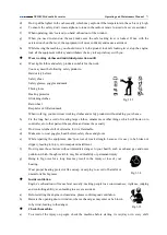
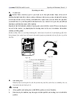
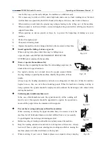
Always verity the following cases to ensure safe locking lever has been pulled to LOCK position.
When transporting the machine
;
When leaving the machine after the duty.
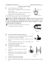
The operation of safe locking lever:
a)
Before leaving the machine:
1)
Place it on level ground, lower the bucket on ground, return all
the control levers to middle position and shut off the engine
correctly.
2)
Pull the safe locking lever to full LOCK position
.
b)
Before starting the engine, confirm that safe locking lever is located at LOCK.
c)
After starting the engine, confirm that all the control levers and pedals are in middle position and
there is no movement in all parts of machine, then lower the safe locking lever to release position.
d)
When all the control levers are in middle position, lower the safe locking lever to release position, if
some part of machine moves, it means there is a failure. At this moment, you should pull the safe
locking lever back to LOCK position and stop the engine. Then you can carry out a repair or contact
with appointed dealer.
Engine’s speed control
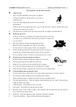
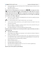
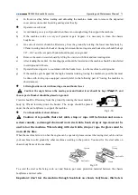
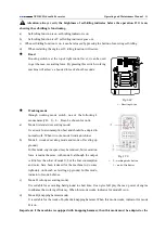
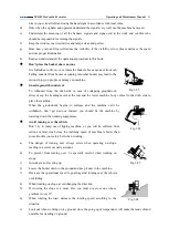
According to this picture, increase or decrease engine speed through engine speed knob on right control box,
a)
Increase engine speed by turning the engine speed knob clockwisely; on the contrary, decrease engine
speed by turning the engine speed knob counter-clockwisely.
b)
Before stopping the engine, always turn the engine speed
knob counter-clockwisely to the bottom (low-speed idling
setting), run the engine for 5 min. to cool it, then turn the key
switch to OFF position to stop the engine.
Note: in every working mode, the highest speed of engine can
only reach the max. one designed by this mode.
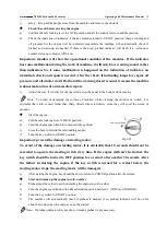
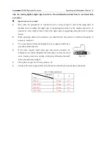
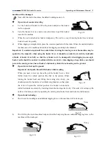
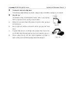
Self-idling speed
In self-idling state, if all the control levers return to middle position,
then after about 4 seconds,
Engine speed will reduce to designed self-idling speed to save the
fuel consumption. If any control lever is operated, engine speed will immediately increase to the designed
one on engine speed knob.
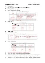
Fig.1-67
1
-
knob of engine speed 2
-
key switch
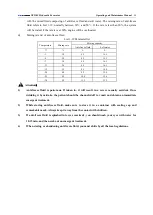
Fig.1-68
1
-
button of canceling self idling
2
-
self idling indicator
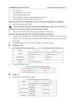
Fig.1-66
1
-
safe locking lever
Low speed
High speed

