background image

1 .  Re

m

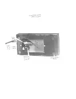
ove the top . 

2. Six  screws hold the asse

m

bly  to the case.  One sheet 

m

etal screw is located just to

the left of the "C" oscillator shield can and one to the left  of the power transfor

m

er

and  fuse  post .  This is the longer of the two screws .  The re

m

aining screws are ac -

cessible by turning t

h

e organ over and re

m

oving the four screws under which are cup

washers . '  The organ should be laid on a pad  or  blanket to protect the keys .

WHITE KEY CAPS 

T

h

e white key caps can be re

m

oved as follows: 

1 .  Re

m

ove the  top of  the organ. 

2. Re

m

ove the small black screw holding t

h

e key cap to the fra

m

e .

.  With the thu

m

b and forefinger grip the front of the key cap and pull forward .  The new

cap can be replaced by reversing  the above procedure. 

BLACK  KEY CAPS 

The black key caps can be re

m

oved as follows: 

1 .  Re

m

ove the top of  the organ . 

2. Re

m

ove the s

m

all black screw  holding  the key cap  to the  fra

m

e.

3

. Depress the two white keys straddling the black key.

4. With the thu

m

b  and forefinger grip the front of the black key and pull forward.  The

new black key cap can be replaced by  reversing  the above procedure.

KEY CONT ACTS 

The key contacts have been factory adjusted and should not require any further adjustments. 

Should the contacts require cleaning,  the following  is  the procedure: 

1 .  Re

m

ove the top . 

2. Remove the keyboard  fro

the console case .  Be sure to  lay the asse

m

bly on a pad.

.  Using a soft brush and denatured alcohol,  the springs and bus&  bars  can be cleaned.

Be careful not to catch any of t

h

e contact springs in  the brush. 

EXPRESSION PEDAL 

The 1

K control found inside of the housing of the Expression Pedal can be c

h

anged as follows: 

1 .  Turn the pedal  over and re

m

ove the cover plate. 

2. The socket head set screw holding the shaft and arm is a No.  6-1/ 4" long screw.  A

No.  6  set screw wrench is used to loosen the screw.

.  The four leads can be unsoldered.  Be sure that the External A

m

plifier lead always 

goes to t

h

e center  lug of  the control. 

4. Re

m

ove the 1/2" nut holding the control to the 

m

ounting plate and remove the  control.

5.  Place the new control  in  the proper position on  the  plate.  Be sure that  the  s

m

all index

ear is positioned  properly  in the hole  found  on the 

m

ounting  plate.  Tig

h

ten the 1/2"

nut.

6. Replace  the four wires.  Be sure that No. 

above is carefully  followed.

7. DO NOT  TIGHTEN THE SET  SCREW.

8 .  Plug the cables into the Co

m

bo and E

xt

ernal Amplifier. 

9. Operate the 16'  - 8' and 4'  stop tabs and rotate the console volu

m

e control on full.

Play a chord on the organ and  with your finger rotate the shaft  of  the new expression

control until maxi

m

um volume is heard out of t

h

e External Amplifier.  The proce­

dure should be done several times to be sure that the 

m

axi

m

um point is reached.  Do

not rotate the shaft any farther than this point .

1

0

.

Hold the shaft  &  depress the  Expression shoe to  the full "ON"  position.

11 .  Tighten the No.  6  set  screw and replace the cover  plate.

Содержание 7300

Страница 1: ...MODEL 7300 ORGAN SERVICE INSTRUCTIONS and PARTS CATALOG PART No 131512 THE WURLITZER CO ELKHART IND T I I t I ...

Страница 2: ......

Страница 3: ...COMBO ORGAN Com i lr z Tran 13053 ...

Страница 4: ...Cable 12 lg 130577 6 lg 130578 EXPRESSION PEDAL 130558 Complete Rubber Bumper 130526 ...

Страница 5: ...AC Cord 130670 Complete M 7300 COMBO ORGAN Bottom Bumpers 130567 Top Screws 76649 12 Washers 15092 1 End Caps 130590 Name Plate 130713 ...

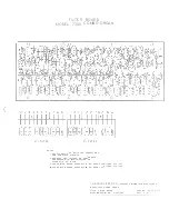
Страница 6: ... just IC s The total range of the audio frequencies handled by the generators is approximately 65 Hz to 8 000 Hz There are two printed circuit boards used One board covers notes from C to F and the other F to B The physical layout of a typical board is shown on drawing No 130677 Both of these printed board circuits are identical Each board contains the same number of discrete components and IC s F...

Страница 7: ...or example the first group of note signals are C to G 9 notes The remaining five groups are 8 notes in length Therefore at position S on the keyboard whenever the first nine keys are depres sed 16 signals will appear on the black wire 8 signals on the purple wire 4 signals on the red wire The pitch of these signals is shown in the chart below the keyboard The other group divisions for the rest of ...

Страница 8: ...a common lead is then wired to the three Stop Switches String Bass and Reed The sound level of these three stops can be set by the solo switch This switch controls a 39 K re sistor 3 across the normal 470 K 2 feedback resistor in the collector base circuit of stage TR 1 With the 39 K 3 resistor across the 470 K 2 greater feedback is provided to lower the level of this stage When the 39 K 3 is remo...

Страница 9: ...he Combo Organ A step down power transformer having two isolated secondary windings is used Silicon diodes are used in a conventional rectifier configuration The low voltage section taken out of diodes D 1 and D 2 is filtered to ground by a large 10 000 mfd capacitor 241 The DC output is then fed to two transistors TR 16 and TR 12 to provide extremely good 3 45 Volts DC regulation This regulated v...

Страница 10: ...re to lay the assembly on a pad 3 Using a soft brush and denatured alcohol the springs and bus bars can be cleaned Be careful not to catch any of the contact springs in the brush EXPRESSION PEDAL The 10 K control found inside of the housing of the Expression Pedal can be changed as follows 1 Turn the pedal over and remove the cover plate 2 The socket head set screw holding the shaft and arm is a N...

Страница 11: ...ve been adjusted the entire organ is tuned because these twelve master top octave notes control the entire range of the organ no matter what stop is used ELECTRONIC UNITS Important Before replacing electronic components indiscriminately the technician should always perform a visual check looking for broken wires cold solder joints etc One of two types of meters are to be used in troubleshooting th...

Страница 12: ...nted Circuit Board 3 Check 1 mfd 110 Capacitor 4 Check Lever Switch 1 Check TR 6 Stage 2 Check J 2 JumP er 3 Check 47 mfd 97 Capacitor 4 Check Lever Switch 1 Check TR 5 Stage 2 Check J 1 Jumper 3 Check 22 mfd 88 Capacitor 4 Check Lever Switch 1 Check TR 4 2 Check 15 mfd 87 Capacitor 3 Check 3 3 K 86 Resistor 4 Check Lever Switch 1 Check wire connections from group signal take off points shown on S...

Страница 13: ...Check Reed Stop Switch 2 Check components numbered 62 63 64 65 R Vibrato dead l Check TR 14 Stage 2 Check TR 13 Stage 3 Check Vibrato Switch 4 Check wire from Vibrato Switch to Generators s All keys sound electri l Check 75 V supply to signal cally noisy on all buss rods of keyboard All stops buss rods should measure 75 V when no keys depressed 2 Check 175 mfd 15 Capacitor in Power Supply ...

Страница 14: ......

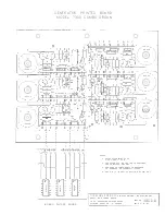
Страница 15: ... F I C AT I O N O N S C H E M AT I C N O 1 3 0 7 1 6 3 S E E P R I N T ED B OA R D A S S E M B LY 8 N O 1 3 0 69 6 F O R I T E M S 2 2 3 2 3 1 4 S E E P RI N T E D BOA R D A S S E M B LY 4 N O 1 3 0 68 1 FO R I T E M S 2 1 4 2 2 2 T H E W U R L I T Z E R CO E L KHART D IVISIO N ELKHART I N D I A N A M OD E L 730 0 C O M BO O R G A N T I T L E F I LT E R BOA R D STA RT I N G S E R I A L N O E 200 0...

Страница 16: ......

Страница 17: ... C B A V N O T E S BOARD ASSEMBLIE S U S E D C T O F AND F T O B 0 _ 1 3 0 5 3 9 I _ C 4 1 3 0 5 3 9 c s I __ 3 C 5 3 9 I _ L G 0 2 S E E S C H E MAT IC 1 3 0 6 8 4 FOR CON N ECT IONS A N D CO M P LETE C I R C U I T S 3 N U M B E R S O N C O M P O N E N T S C O R R E S PO N D TO NUM B E R S O N S C H EMAT I C 1 3 0 6 8 4 4 DOT O N J C I N D I C AT E S PO S I T I O N OF P I N N O I T H E W U R L I ...

Страница 18: ......

Страница 19: ... 100V Capacitor 056 MFD lO0V Capacitor 047 MFD 100V Capacitor 039 MFD 100V Capacitor 033 MFD lO0V Capacitor 027 MFD lO0V Capacitor 022 MFD l00V Capacitor 018 MFD lO0V Capacitor 015 MFD lO0V Capacitor 012 MFD l O0V Capacitor 01 MFD lO0V Capacitor 0068 MFD lOOV Capacitor 0056 MFD lO0V Capacitor 0047 MFD DISC Capacitor 0033 MFD DISC Capacitor 0018 MFD DISC Capacitor 001 MFD DISC Capacitor 820 MMFD DI...

Страница 20: ...30509 130597 130598 130599 Escutcheon Casting Switch Brkt Wire Assembly Button Mtg Pl Switch Assembly Switch ON OFF Control Neon Glow Lamp Speed Nut Sleeving Switch M tg Brkt Assembly Switch Switch EXPRESSION PEDAL ASSEMBLY COMPLETE 13055 8 130572 1305 26 1305 22 Felt Pad Rubber Bum per Rubber Pad LEG ASSEMBLY COMPLETE 130560 130705 130706 Thum b Screw Special Nut ...

Страница 21: ......

Страница 22: ......

Отзывы: