TUNIN
G
The generators
i
nclud
i
ng the
m
aster osc
i
llators have been carefull
y
tuned at the factor
y
and
should not requ
i
re an
y
tun
i
ng unless so
m
e co
mp
onent
i
n the "
m
aster osc
i
llator stage" has been
changed. The tun
i
ng cons
i
sts of adjust
i
ng t
w
elve tun
i
ng slugs controll
i
ng the to
p
octave notes .
Tun
i
ng
wi
ll requ
i
re the use of a Strobo-Tuner
i
nd
i
cator and an
i
nsulated tun
i
ng hex-head
w
rench.
G
eneral Ce
m
ent No. 8606 or
W
alsco No. 2543. The
p
rocedure
i
s as follo
w
s:
1 . Re
m
ove the to
p
.
2. Un
p
lug the cable to the External A
mp
l
i
f
i
er and
p
lug th
i
s end
i
nto the Strobo-Tuner.
The level of the s
i
gnal to dr
i
ve the Strobo-Tuner can be controlled b
y
the E
xp
ress
i
on
Pedal.
3. Before atte
mp
t
i
ng an
y
tun
i
ng, the techn
i
c
i
an should v
i
susll
y
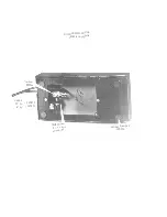
locate the tun
i
ng slugs
for each note. The sh
i
eld cans are
p
ro
p
erl
y m
arked. Turn
i
ng the slug
wi
th the hex
head
w
rench clock
wi
se
wi
ll decrease the
pi
tch or flatten the note; turn
i
ng the slug
counter-clock
wi
se
wi
ll
i
ncrease the
pi
tch or shar
p
en the note.
4. Cancel all sto
p
s on the organ.
5 . Move the 8' Sto
p
to the h
i
ghest
p
os
i
t
i
on .
6. The second octave,
w
h
i
ch ar-e the ke
y
s fro
m
C-13 to B-24,
wi
ll be used for the tun
i
ng.
7. De
p
ress ke
y
C-13 and observe the Strobo-Tuner. If the note
i
s not
i
n tune, the slug
should be rotated unt
i
l the Strobe
p
attern stands st
i
ll .
8. All the other notes
i
n the octave are handled the sa
m
e
w
a
y
.
W
hen all the t
w
elve slugs
have been adjusted, the ent
i
re organ
i
s tuned, because these "t
w
elve
m
aster" to
p
octave notes control the ent
i
re range of the organ no
m
atter
w
hat sto
p i
s used.
ELECTRONIC UNI
T
S
I
m
portant - Before re
p
lac
i
ng electron
i
c co
mp
onents
i
nd
i
scr
imi
natel
y
the techn
i
c
i
an should al
w
a
y
s
p
erform a v
i
sual check look
i
ng f
o
r broken
wi
res, cold solder jo
i
nts, etc .
One of t
w
o t
yp
es of
m
eters are to be used
i
n troubleshoot
i
ng the electron
i
c un
i
ts - a Vacuu
m
Tube
Voltoh
my
st or a 20, 000 ohms
p
er volt
m
eter.
A conven
i
ent s
i
gnal trac
i
ng probe and s
y
ste
m
can be e
mp
lo
y
ed b
y
us
i
ng the
i
n
p
ut
p
hone
p
lug out
of the Express
i
on Pedal Cable and touch
i
ng s
i
gnal
p
o
i
nts
i
n the Co
m
bo s
y
ste
m
. For exa
mp
le, the
out
p
ut s
i
gnal from the generators can be
p
robed and heard at the IC' s or the ke
y
board b
y
touch
i
n
g
the
p
hone
p
lug center to an
y
o
f
the nu
m
bered
p
o
i
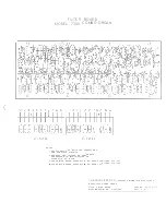
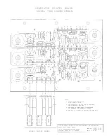
nts found on Sche
m
at
i
cs No. 130684 and
1
30708.
Th
i
s
p
rocedure can qu
i
ckl
y i
solate the serv
i
ce to e
i
ther the generator or the ke
y
board.
The follo
wi
ng troubleshoot
i
ng suggest
i
ons are g
i
ven
i
n chart for
m
and cover the
m
ajor
i
t
y
of
serv
i
ce the techn
i
can
m
a
y
be called on to
p
erfor
m
:
I
.
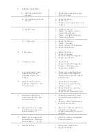
COMBO DEAD
A . Neon
pi
lot la
mp
off
B . P
i
lot la
mp
on
No hu
m
or no
i
se out of the
s
y
ste
m
.
C . P
i
lot la
mp
on.
Onl
y
hu
m
or no
i
se out of
the s
y
ste
m
.
CHECK
1
. ON/OFF S
wi
tch
2
.
Fuse
3 . Po
w
er cord connect
i
on .
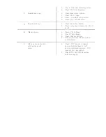
1 . Cables to E
xp
ress
i
on Pedal.
2. Check TR-8 and TR-9 Stages.
3 . Check M Br
i
ghtness Control.
1. Check 10 V and
1
4.8 V to Master
Osc
i
llator .
2. Check 3 .45 V to IC's
3. Check TR-8 and TR-9 Stages.
4 . Check Phone Jack .
5 . Chec
k
E
xt
ernal Am
p
l
i
f
i
er .
6. Ch
e
ck set scre
w
on Ex
p
ress
i
on
Control Pot .
Содержание 7300
Страница 2: ......
Страница 3: ...COMBO ORGAN Com i lr z Tran 13053 ...
Страница 4: ...Cable 12 lg 130577 6 lg 130578 EXPRESSION PEDAL 130558 Complete Rubber Bumper 130526 ...
Страница 14: ......
Страница 16: ......
Страница 18: ......
Страница 21: ......
Страница 22: ......


