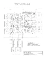
related and wired directly to the keyboard. This "IC stage then feeds the next IC stage to further
divide the signal and again two outputs are available shown as letters H and F and numbered
points 22* and 10* wired to the keyboard. The original A signal started out as 7040Hz. and
through successive IC circuit dividers finally ended up at ll0 Hz the lowest A found in the combo
organ . The signal feeding one IC to another IC is from Pin 9 to Pin 2 . The voltage to drive
the IC circuits is wired to Pin 11 of each IC and shown on the schematic as letter V + 3 .45V.
Ground for all the IC' s is shown as the letter G. Note that three IC' s - Part No. 130680, are
mounted on a printed board. All of these boards are identical. The frequencies are numbered
from the lowest l * to the highest 84*. These same numbers will be found on the Keyboard
Schematic No. 130708. All of the other notes are read the same way as the "A" note described
above . Tuning procedure and suggested troubleshooting data will be given in another section.
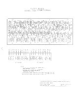
The Keyboard - Refer to Schematic No. 130708
The keyboard consists of 49 keys from C No. l Bass end to C No. 49 Treble end. The under
neath side of the keyboard is shown on the drawing. The keyboard wiring is shown in chart
form. With the exception of the master wires from the generator signals to the keyboard all
of the wiring is part of the printed foil of the keyboard. The master wires, all color coded in
accordance with the color code schedule shown on Schematic 130708, are soldered to Meleo
pins located on the back of the keyboard and numbered from l through 84. These are the num -
bered Qins from the bass end to the treble end. The 84 signals are then isolated by 6. 8 K
resistors or 100 K resistors before being wired through printed copper foil to each key contact
spring. A typical key signal schematic is shown on the drawing. Note that the 16' - 8' - 4'
signals are isolated with a 6.8 K resistor and the mixture - 2-2/3' - 2' - 1-3/5' - l' signals
are isolated with an 100 K resistor.
When a key is depressed, the contact springs roll against signal buss rods. The signal buss
rods for the 16' - 8' - 4' rows of contacts are broken down into six groups shown as lettered
points S - T - V - W - X - Y and identified notewise as shown in the schedule. For example,
the first group of note signals are C to G# - 9 notes . The remaining five groups are 8 notes
in length. Therefore, at position S on the keyboard whenever the first nine keys are depres -
sed 16' signals will appear on the black wire - 8' signals on the purple wire - 4' signals on
the red wire . The pitch of these signals is shown in the chart below the keyboard. The other
group divisions for the rest of the keyboard are handled the same way. These group signals
will be shown on the Sound and Filter System Drawing No. 130716 as small boxes going into
the filters .
The Mixture Bus.s is a single continuous wire, When single keys are played from C-1 to B-36,
four signals appear on this buss; keys from C - 37 to G - 44 three signals; keys from G# - 45
1:o B- 48 two signals; and the last key C - 49 a single signal. The pitch of these signals is
shown in chart form and again these numbers correspond to points found on the Generator,
Schematic No. 130684. Key cap replacements and troubleshooting of this unit is covered in
a separate section .
Sound and Filter System - Refer to Schematic 130716
The generator and keyboard supplies all the signals for the different tonal voices of the filters
before amplification. The group signal from the keyboard for the 16' - 8' - 4' Flute is shown on
the schematic as rectangular boxes - Example: (1)\
-165-104!.
The figures in the boxes
refer to the approximate frequency range of this group. A 16' signal path will be described
from the keyboard through the 16' Flute Filter, switching and amplifier. The example used
is the first group of nine signals shown on the schematic in the upper left. Signal group l -
!65 -104/ is wired by means of a black coded wire to a passive filter consisting of capacitors
and resistors numbered on the schematic as 202, 203, 204, 201, and 200. This filter shapes
the signal to a proper flute tone. The shaped signal is then fed through numbered components
199 and 205 into the base of TR-7 labeled the 16' Pre-Amplifier. The transi�tor is properly
biased to amplify the signal. From the collector of TR-7, the signal path is through numbered
components ll0 and lll to the common of the 16' Stop Switch. At the switch this signal can
be picked off at four different sound levels before wiring to a Brightness Control marked M
on the organ. This control will, as it is moved from the "OFF" position to the "ON" position,
accent the treble quality of the signal. The modified signal will then appear across the l . 8
Содержание 7300
Страница 2: ......
Страница 3: ...COMBO ORGAN Com i lr z Tran 13053 ...
Страница 4: ...Cable 12 lg 130577 6 lg 130578 EXPRESSION PEDAL 130558 Complete Rubber Bumper 130526 ...
Страница 14: ......
Страница 16: ......
Страница 18: ......
Страница 21: ......
Страница 22: ......


